Paste coating machine and coating method

A coating machine and paste technology, applied in the field of paste coating machine, can solve the problems of increased weight of the door frame, vibration of the device, difficulty in coating the paste pattern, etc., to prevent the reduction of production takt time, The effect of suppressing vibration

Inactive Publication Date: 2007-08-08
AIMECHATEC LTD
View PDF8 Cites 0 Cited by
  • Summary
  • Abstract
  • Description
  • Claims
  • Application Information

AI Technical Summary

Problems solved by technology

Therefore, when the paste pattern is applied at high speed, due to the movement of the workbench, vibrations in the XYZ direction occur on each part of the device, and it is difficult to apply the paste pattern uniformly into the desired shape.
In addition, when moving the nozzle side instead of the XYθ table, it is necessary to move the gantry on which the nozzle is installed. When the size of the substrate increases, the weight of the gantry also increases, and the entire device vibrates when moving. , the same problem occurs when moving the workbench

Method used


Image

  • Paste coating machine and coating method
  • Paste coating machine and coating method
  • Paste coating machine and coating method

Examples


Embodiment Construction

[0019] Embodiments of the present invention will be described below with reference to the drawings.

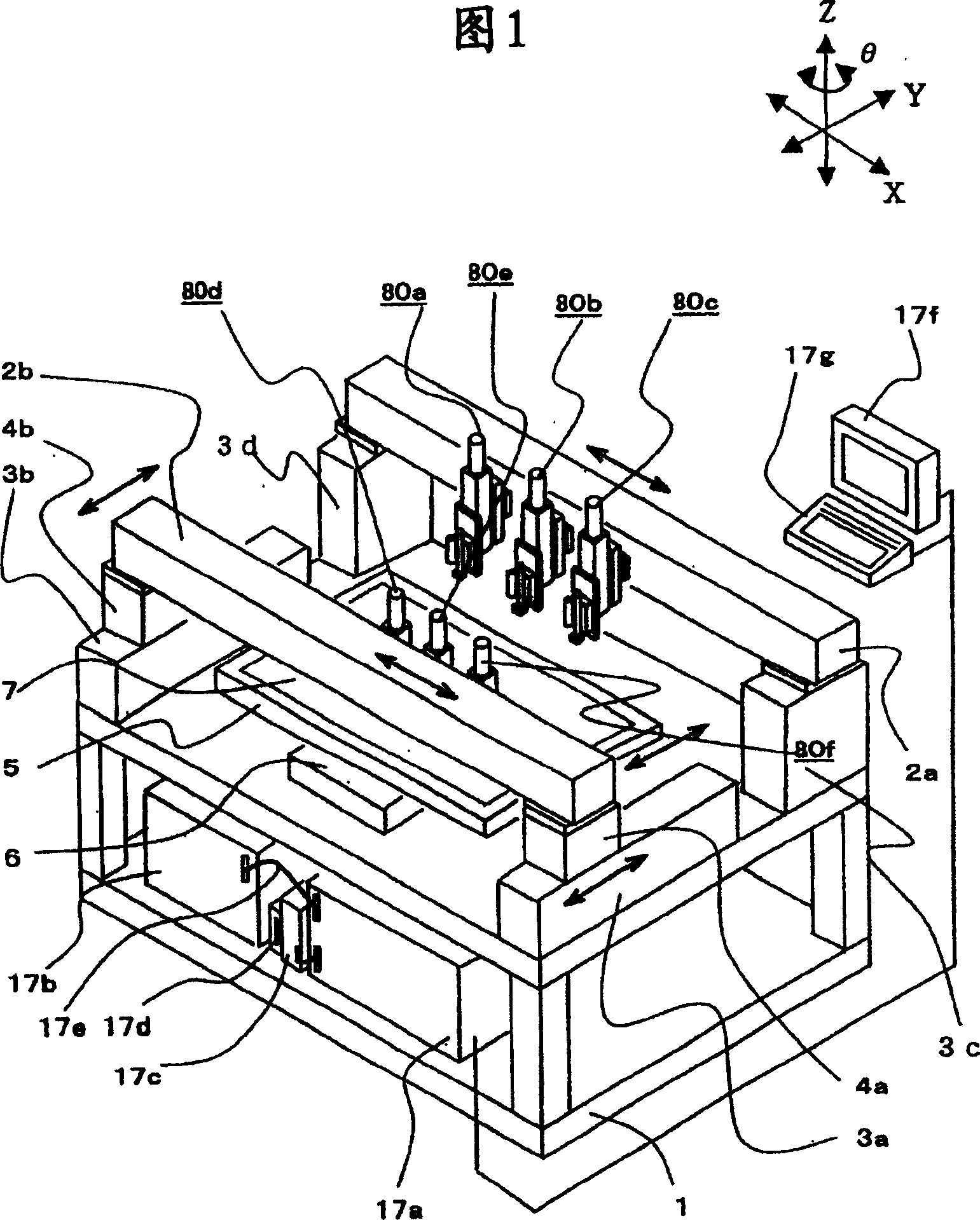
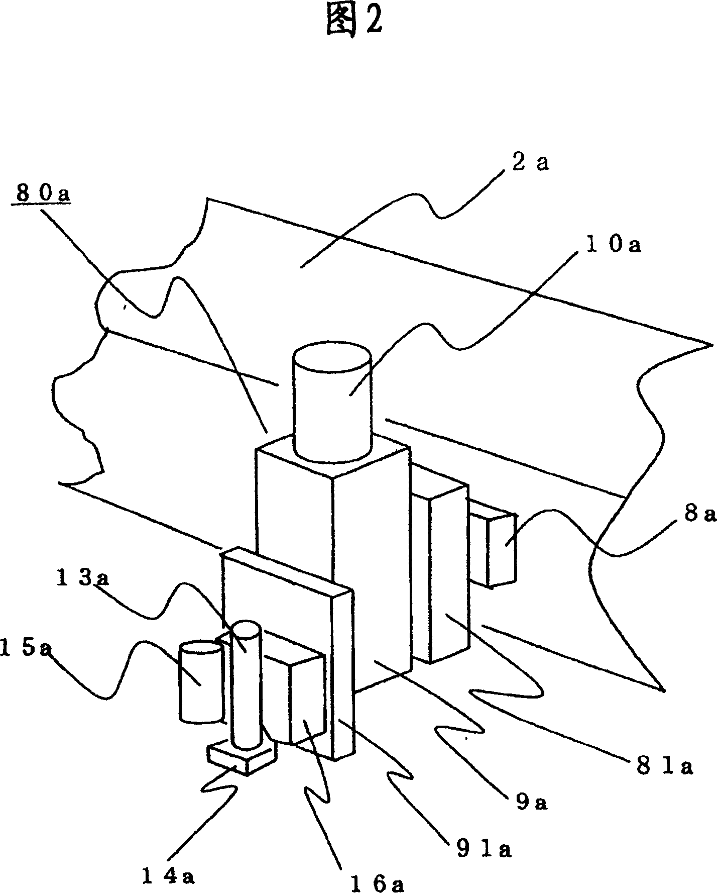
[0020] Fig. 1 is a perspective view showing one embodiment of a paste applicator according to the present invention. FIG. 2 is an enlarged view of the coating head 80a.

[0021] A plurality of beams 2a, 2b of coating heads 80a to 80f for coating paste are provided facing each other on the bracket 1, wherein one of the beams can change the interval between the brackets in the Y-axis direction. In addition, the beams 2a and 2b are equipped with a coating head X-axis moving mechanism (with the adjustment of the interval in the X-axis direction). That is, although not shown in figure specifically, linear motors 8a-8f are provided for each coating head on beams 2a, 2b so that each coating head can move. In the coating head 80a, as shown in FIG. 2, Z-axis moving table support brackets 81a-81f are provided on the linear motors 8a-8f. Z-axis moving tables 9a-9f and Z-axis servomoto...


PUM


Abstract

The invention discloses a coater and a coating method dealing with the problem that when the glass sheet in 2 m is used in manufacturing the liquid crystal panel. In such situation, the device gets enlargement when coating the paste (bonding agent) on the substrate surface. When the manufacture time is reduced and the coating speed is increased, the vibration is generated in the corner which can reduce the coating precision. The invention adopts a speed control when coating the corner, which means switching the relative speed change of the substrate and the nozzle in two-stage. Simultaneously, in order to keep the coating amount constant, two pressure regulators and high-speed changeover valves are arranged in the coater, and a pneumatic loop is also arranged in the coater, which can conveniently change over the pneumatic loop in two stages controlling coating amount at high speed.

Description

technical field [0001] The present invention relates to a paste coating machine and a coating method for coating a paste in a predetermined pattern on a predetermined position on a substrate surface. Background technique [0002] Conventionally, as a paste coating machine for applying a paste (adhesive) on one substrate constituting a liquid crystal panel and sticking it to another substrate, as disclosed in JP-A-2003-266005, When coating the corners of a quadrangular pattern, the vibration is measured with a distance meter that measures the relative distance between the substrate and the nozzle, and the location where the vibration occurs and the mode of the vibration are measured in advance. A vibration pattern with an opposite phase is generated at the position of this vibration, and the occurrence of vibration is suppressed. [0003] However, since the size of the substrate becomes larger than 1m×1m, when the stage on which the substrate is placed moves in the XYθ direc...

Claims


Application Information

Patent Timeline
Patent Type & Authority Patents(China)
IPC IPC(8): B05C11/10B05C5/00B05D1/40B05D1/26B05C11/00B05D1/12G02F1/13
CPCB05C5/0225B05C11/1002B05D1/26G02F1/1303G02F1/1339H01L21/6715
Inventor 石田茂川隅幸宏松井淳一山间伸也圆山勇神田广造赤塚一义
Owner AIMECHATEC LTD
Why Eureka
Try Eureka