Cathode-ray tube display device

A technology for display devices and cathodes, which is applied to cathode ray tube indicators, cathode ray tubes/electron beam tubes, electrode devices and related components, and can solve problems such as obvious image noise and increased image noise

Inactive Publication Date: 2002-11-27
MITSUBISHI ELECTRIC CORP
View PDF0 Cites 0 Cited by
  • Summary
  • Abstract
  • Description
  • Claims
  • Application Information

AI Technical Summary

Problems solved by technology

[0013] However, in such a CRT display device, high brightness can be obtained on the one hand, but by increasing the sensitivity of the output current of the CRT corresponding to the driving voltage, even in the case of low-tone display, even if it is not obvious in the existing CRT display device Image noise also becomes larger, resulting in obvious disadvantages of image noise

Method used


Image

  • Cathode-ray tube display device
  • Cathode-ray tube display device
  • Cathode-ray tube display device

Examples


Embodiment 2

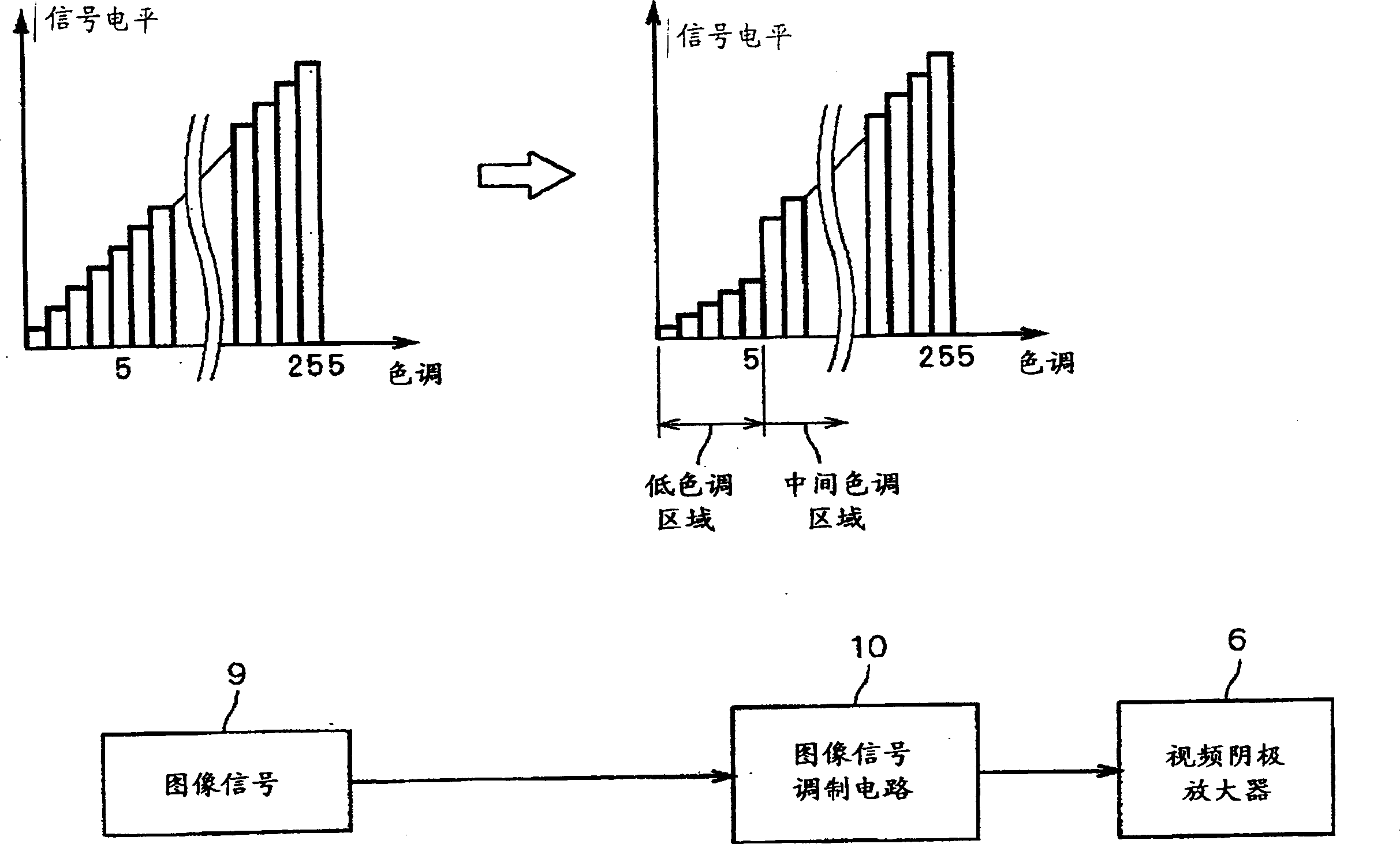
[0060] For example in figure 2 In the second image signal shown, the shift of the signal level is larger in the low-tone region where the signal level is suppressed than in the first image signal, and in the boundary between the mid-tone and high-tone regions other than that. In the case of using such a second image signal, the image is displayed with a lower color tone due to the color tone in the vicinity of the boundary. Since this boundary exists in a relatively low tone region, there is a problem that the tone of particularly dark graphics (for example, a night scene) is significantly reduced in an image that displays a lot of black with low tone.

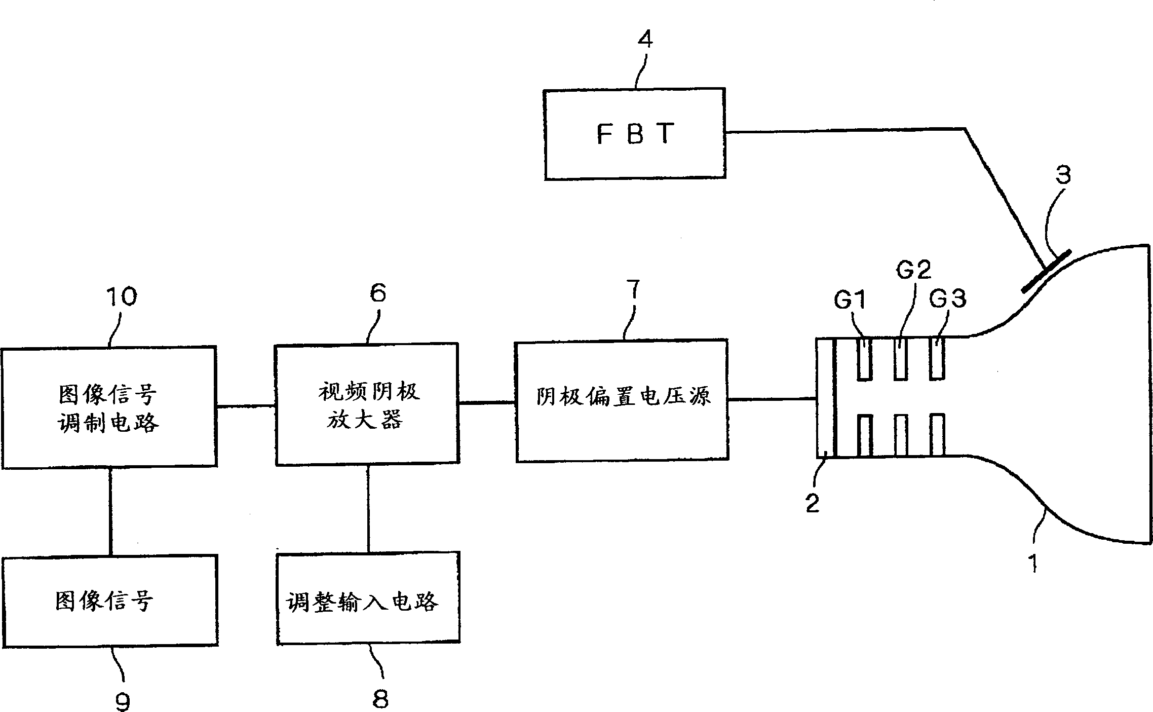
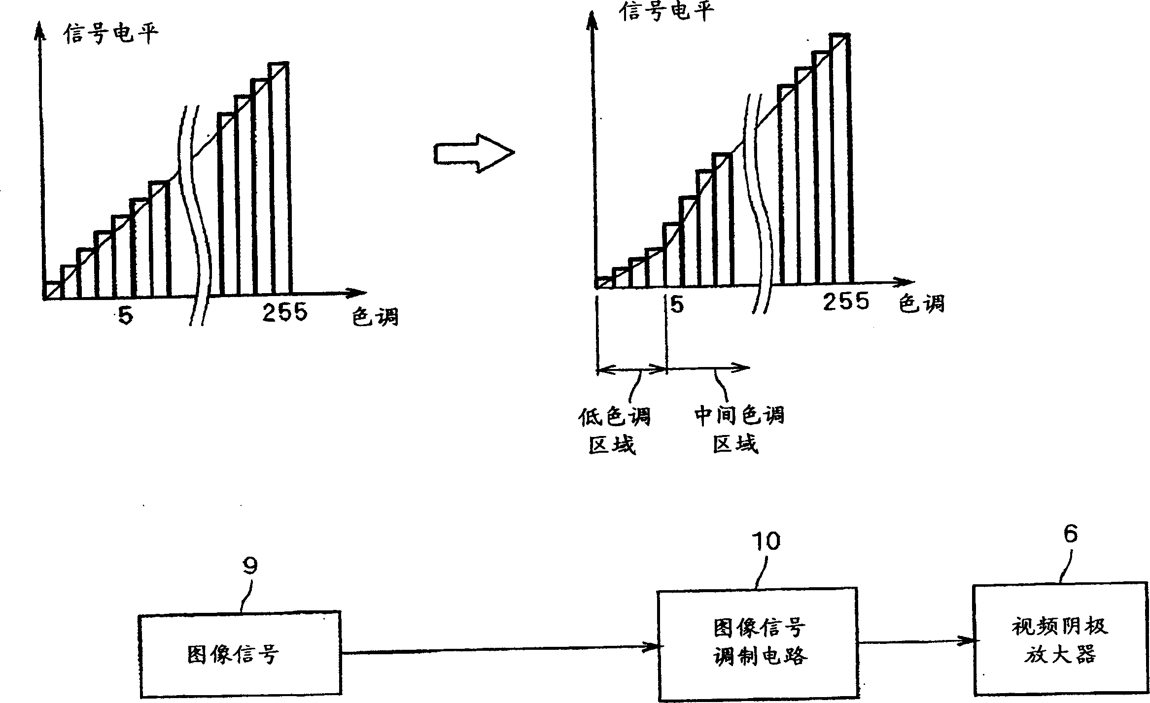
[0061] In Embodiment 2, this problem should be solved by suppressing abrupt changes in the signal level at the boundary between the signal level of the low-tone area and the signal level of the high-tone area in the second image signal output from the image signal modulation circuit 10 .

[0062] image 3 It is a figure exp...


PUM


Abstract

In a CRT display device equipped with a CRT (MM tube) that is brighter than conventional CRTs, image noise in low-brightness areas is made inconspicuous while improving contrast. The image signal modulation circuit 10 converts the image signal 9 (first image signal) into a second image signal in which the signal level of a low-tone area is suppressed lower than that of the first image signal. As a result, since the cathode bias voltage source 7 generates the drive voltage based on the second image signal, the drive voltage in the low-tone area is kept low, and the brightness of the low-tone area in the CRT 1 becomes low. Therefore, the image noise in the low-brightness part is made inconspicuous, and the contrast value is increased to improve the display quality.

Description

technical field [0001] The present invention relates to a CRT display device using a cathode ray tube. Background technique [0002] Figure 4 It is a schematic structural diagram of a conventional general CRT display device. 1 is a CRT. As shown in the figure, CRT1 includes an electron gun including a cathode 2 for emitting electrons, a first electrode G1, a second electrode G2, a third electrode G3, an anode 3, and the like. The first electrode G1, the second electrode G2, and the third electrode G3 are cylindrical electrodes having electron passage holes arranged in the electron gun, and are used for extraction of electrons from the cathode 2, prefocusing, and the like. To simplify the description, the focusing electrodes and the like arranged after the third electrode G3 are omitted. Also, 4 is a flyback transformer (FBT), and 5 is a variable resistor. 6 is a video cathode amplifier that amplifies the image signal, 7 is a cathode bias voltage sour...

Claims


Application Information

Patent Timeline
Patent Type & Authority Applications(China)
IPC IPC(8): H04N3/18G09G1/00G09G1/04G09G3/00H01J23/16H01J29/46H01J29/48H01J29/52H04N5/20H04N5/66H04N5/68H04N9/00
CPCH01J29/488H01J2229/4844H04N5/20H04N5/68H04N3/18
Inventor 中村芳知重松晴夫瓶子晃永安井裕信
Owner MITSUBISHI ELECTRIC CORP
Why Eureka
Try Eureka