Low coherence multiplex optical fiber interferometer based on non-balanced Mach-Zehnder optical autocorrelator

A technology of optical fiber interferometer and autocorrelator, which is applied in the direction of using optical devices, using optical devices to transmit sensing components, instruments, etc., can solve the problems of identification and sensor measurement difficulties, large light source power attenuation, and sensors are no longer unique. Achieve the effects of suppressing optical path matching interference noise, enhancing utilization efficiency, and avoiding instability

Inactive Publication Date: 2011-03-30
HARBIN ENG UNIV
View PDF9 Cites 10 Cited by
  • Summary
  • Abstract
  • Description
  • Claims
  • Application Information

AI Technical Summary

Problems solved by technology

Due to the light-splitting characteristics and optical path symmetry characteristics of the N×M fiber coupler, the above-mentioned optical autocorrelators have three problems without exception: one is that the optical path topology has a large attenuation of the light source power and low light source utilization
Taking the 2×2 fiber optic coupler as an example, only half of the optical signal generated by the light source reaches the sensor array, and half of the optical signal reflected by it is attenuated, so that image 3 As far as the light path structure disclosed by W.V.Sorin is concerned, theoretically at most only 1 / 4 of the light source power participates in the optical correlation process, and other power is attenuated. If a 3×3 or 4×4 fiber coupler is used, its Power attenuation is (1 / 3) 2 or (1 / 4) 2 , it is even more serious; the second is certain optical path structures, the optical signal passes through the optical path autocorrelator twice (or multiple times) before and after, such as: Chinese patent application No. The network sensing demodulation device (Chinese patent application number: 200810136821.2) makes the optical signal correlation between the optical fiber sensor and the optical path autocorrelator have more than two optical path matching relationships, resulting in a secondary (or multiple) optical path matching relationship in the white light interference signal. Second) the optical path matching noise makes the sensor autocorrelation peak no longer unique in the spatial position, which makes it difficult to identify and measure the sensor; thirdly, there is symmetry in the optical path topology, and the light source and the detector are symmetrical in the optical path. Reciprocal, theoretically at least the optical signal with the same value as the received power of the detector is fed back to the light source. Although the type of light source is wide-spectrum light, compared with the laser light source, it is not very sensitive to feedback, but the excessive signal Power feedback will cause the resonance of the light source (such as the light source ASE based on the fiber spontaneous super-radiation type, etc.), which will lead to a reduction in the power of the light signal generated by the light source, especially in the case of white light interference, large interference signal power fluctuations will affect the use of the light source It will cause extremely adverse effects and reduce the measurement accuracy of the optical self-coherence peak amplitude

Method used


Image

  • Low coherence multiplex optical fiber interferometer based on non-balanced Mach-Zehnder optical autocorrelator
  • Low coherence multiplex optical fiber interferometer based on non-balanced Mach-Zehnder optical autocorrelator
  • Low coherence multiplex optical fiber interferometer based on non-balanced Mach-Zehnder optical autocorrelator

Examples


Embodiment Construction

[0055] The present invention is described in more detail below in conjunction with accompanying drawing example:

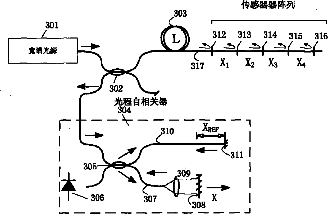
[0056] A scheme for distributed optical fiber sensing measurement system based on unbalanced Mach-Zehnder structured optical autocorrelator, such as Figure 5 shown. Depend on Figure 5 It can be seen that the distributed optical fiber white light interference sensor array is composed of a wide-spectrum light source 1, an unbalanced Mach-Zehnder optical autocorrelator 2, an optical path autocorrelation detection unit 3, a transmission optical fiber 4, and an optical fiber sensor array 5 connected end to end. Unbalanced Mach-Zehnder optical autocorrelator 2 is made up of the first fiber coupler 21, three-port optical circulator 23, fiber collimator 24, movable optical mirror 25 and the second fiber coupler 26; The detection unit 3 is composed of three-port optical circulators 31 , 33 and optical detectors 32 , 34 .

[0057] Such as Figure 5 shown. When the st...


PUM


Abstract

The invention provides a low coherence multiplex optical fiber interferometer based on a non-balanced Mach-Zehnder optical autocorrelator. The optical fiber interferometer is formed by successively connecting a wide-spectrum light source (1), the non-balanced Mach-Zehnder optical autocorrelator (2), an optical distance autocorrelation detection unit (3), a transmission optical fiber (4) and an optical fiber sensor array (5) from end to end, wherein the non-balanced Mach-Zehnder optical autocorrelator (2) is composed of a first optical fiber coupler (21), a three-port optical circulator (23), an optical fiber collimator (24), a moveable optical reflector (25) and a second optical fiber coupler (26); and the optical distance autocorrelation detection unit (3) is composed of a three-port optical circulator (31) or (33), a photodetector (32) or (34). The optical fiber interferometer can be applied to the fields such as real-time monitoring and measurement of multipoint strain or temperature and other physical quantities, monitoring of large-sized intelligent structures and the like.

Description

technical field [0001] The invention belongs to the field of optical fiber technology, and in particular relates to a low-coherence multiplexing optical fiber interferometer based on a Mach-Zehnder optical autocorrelator. Too low and increase system stability and other issues. Background technique [0002] Fiber-optic interferometers driven by low-coherence, broadband light sources such as light-emitting diodes (LEDs), superspontaneous emission sources (ASEs) or superluminescent laser diodes (SLDs) are often referred to as white-light fiber interferometers. The structure of a typical fiber optic white light interferometer is as follows: figure 1 As shown, the Michelson-type interferometer built by single-mode optical fiber uses a wide-spectrum light source LED or ASE as the light source, and realizes the measurement of the physical quantity to be measured through the white light interference fringes detected by the detector. Its working principle is as follows, after the b...

Claims


Application Information

Patent Timeline
IPC IPC(8): G01D5/26G01B11/16
Inventor 苑勇贵杨军苑立波
Owner HARBIN ENG UNIV
Why Eureka
Try Eureka