
High-power density motor with multidirectional magnetic field

A high power density, magnetic field technology, applied in electrical components, electromechanical devices, magnetic circuit static parts, etc., can solve the problems of easy knocking, reduced operating efficiency, inter-turn short circuit, etc. The effect of high performance, high flux utilization, and low leakage flux

Inactive Publication Date: 2011-03-16
HARBIN ENG UNIV
View PDF8 Cites 4 Cited by
  • Summary
  • Abstract
  • Description
  • Claims
  • Application Information

AI Technical Summary

Problems solved by technology

[0003] (1) The magnetic field formed when the armature current flows through the end of the winding belongs to the leakage magnetic field. The existence of the leakage magnetic field will cause the waveform distortion of the main magnetic field of the air gap and increase the saturation degree of the core;
[0004] (2) The end of the winding is located outside the core slot, which is easy to be damaged by bumping when the motor is disassembled, and inter-turn short circuit or open circuit fault occurs, and in some transient processes of the motor, the excessive armature current impact will cause broken ends;
[0005] (3) Although the end of the winding does not participate in electromechanical energy conversion, it also needs to consume a certain amount of copper wire and generate corresponding copper loss, which will increase the cost, volume and weight of the motor and reduce the operating efficiency
[0008] (2) In these motors, the stator windings are not fully utilized, and there are still end structures with traditional windings
[0009] (3) There are no left and right end rotor structures similar to the present invention, stator annular groove structure, specific structures such as stator and rotor magnetic isolation measures
[0010] (4) Does not have and cannot realize the structure and function of eliminating the cogging moment proposed by the present invention

Method used


Image

  • High-power density motor with multidirectional magnetic field
  • High-power density motor with multidirectional magnetic field
  • High-power density motor with multidirectional magnetic field

Examples


Embodiment approach 1

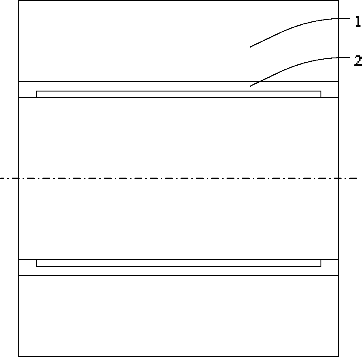
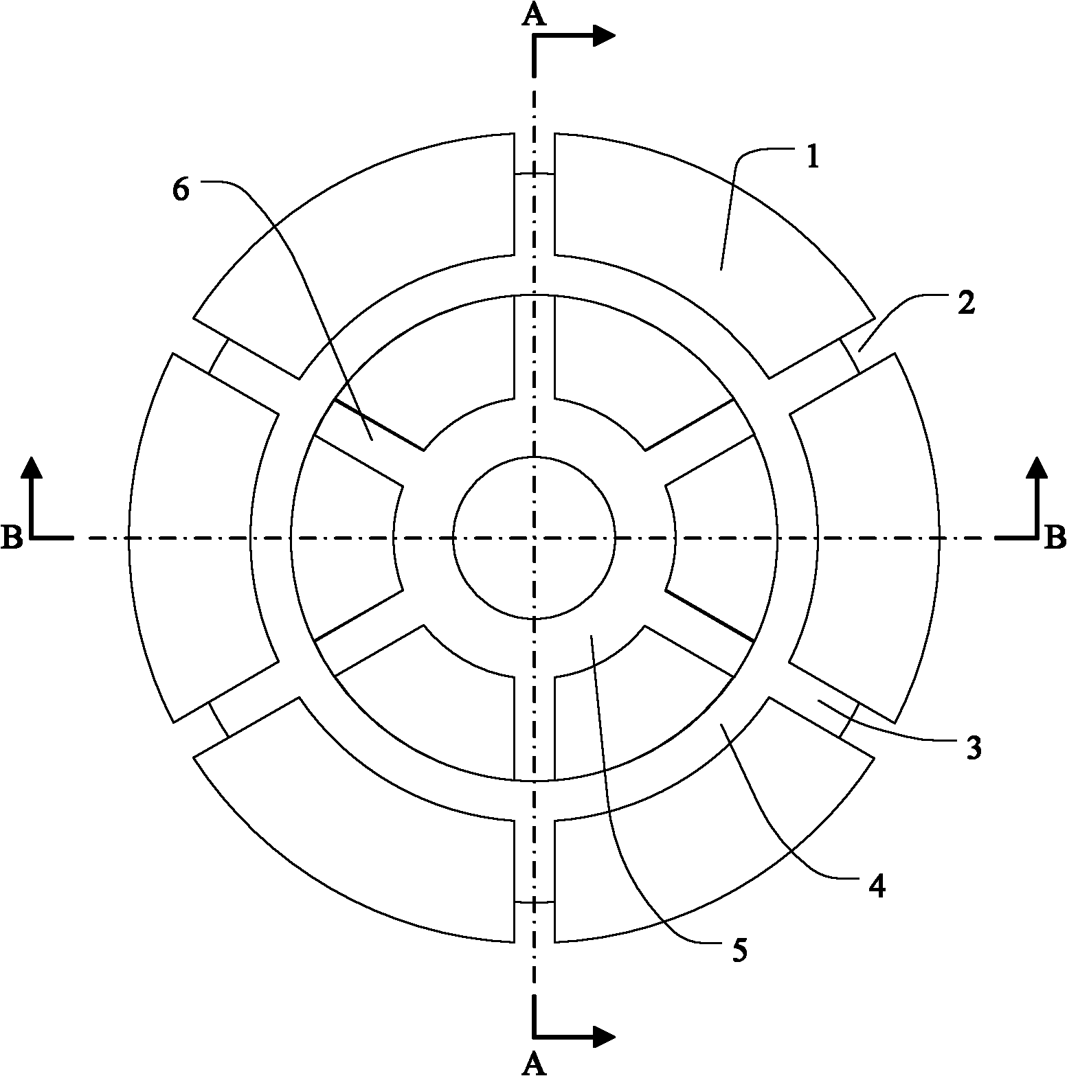
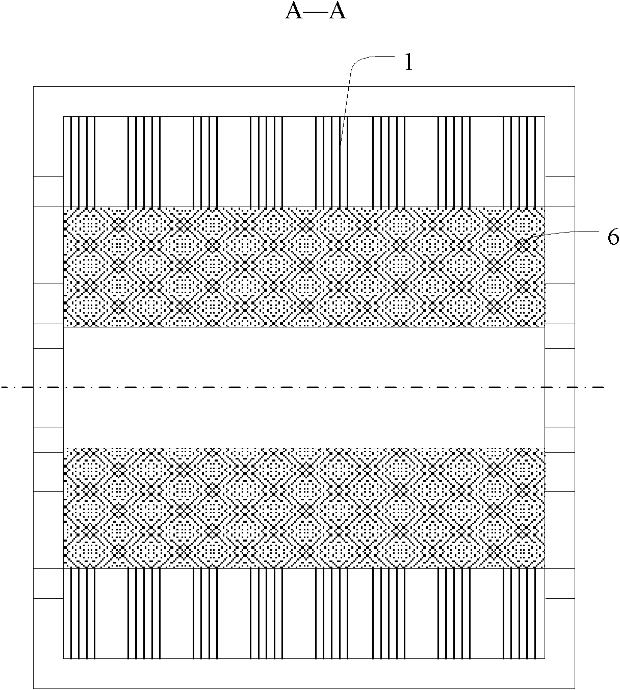
[0041] The high power density motor with the structure of the present invention is composed of several main parts such as a stator, an intermediate rotor, a left end rotor, a right end rotor, a left end bearing, a right end bearing, and a hollow shaft, specifically including: a stator core 1; slot 2, radial slot 3, annular slot 4; stator magnetic isolation ring 5 and stator magnetic isolation plate 6 inside stator core 1; stator winding 7; cable 8 for connecting stator winding 7 and external power supply; The hollow shaft 9 of the line hole 10; the rotor core 11 of the left end rotor and the right end rotor; the outer ring main magnetic pole 12 and the inner ring main magnetic pole 13 pasted on the rotor iron core 11 of the left end rotor and the right end rotor; the rotor cores of the left end rotor and the right end rotor 11 Internal end rotor magnetic isolation ring 14 and end rotor magnetic isolation plate 15; intermediate rotor core 16; intermediate rotor magnetic isolatio...

Embodiment approach 2

[0061] When the controller of the motor needs to detect the position of the motor rotor, Hall sensors can be embedded in the cylindrical surface of the stator core 1, the end faces on both sides, or in the axial groove 2 and the radial groove 3. The specific placement method is the same as that of the existing permanent magnet. The placement method of the magneto is the same, and the input and output lines of the Hall sensor are connected to the external controller through the cable 8 .

[0062] Others are the same as the above embodiment.

Embodiment approach 3

[0064] In order to further eliminate the influence of cogging torque on the performance of the motor, while adjusting the α angle, the geometric centerlines of the radially opposite outer ring main magnetic poles 12 and inner ring main magnetic poles 13 on the left and right end rotors can be staggered by a certain angle, The size of this angle is not easy to exceed the slot pitch angle corresponding to the axial slot 2, and the specific value should be obtained through electromagnetic calculation according to actual requirements.

[0065] Others are the same as the above embodiment.


PUM


Abstract

The invention provides a high-power density motor with a multifunctional magnetic field, which comprises a stator, a middle rotor, a left rotor, a right rotor, a left bearing, a right bearing and a hollow shaft, wherein the stator is fixed on the hollow shaft; the left and right rotors are positioned on the left and right sides of the stator respectively and connected with the hollow shaft through the left bearing and the right bearing respectively; the middle rotor is positioned between the left and right rotors and fixedly connected with the left and right rotors respectively; and the hollow shaft is fixed with other outside devices. The high-power density motor is an outer rotor permanent motor characterized in axial, radial and transverse magnetic field motors. The structure of the traditional motor and the placement mode of armature winding are improved and the end part of the winding can also be participated in the electromechanical energy conservation of the motor, so that the power density and the overall performance of the motor are improved.

Description

technical field [0001] The invention relates to a motor. , especially relates to an outer rotor permanent magnet motor that simultaneously has the characteristics of an axial, radial and transverse field motor. Background technique [0002] The armature winding of an electric motor consists of a plurality of conductor edges placed in the core slots and winding ends for connecting these conductor edges. During the working process of the motor, the edge of the conductor located in the core slot cuts the main magnetic field of the air gap to generate an induced electromotive force and realize electromechanical energy conversion. The end of the winding is located outside the main magnetic field of the air gap, not only does not participate in the electromechanical energy conversion of the motor, but also has the following adverse effects on the performance of the motor: [0003] (1) The magnetic field formed when the armature current flows through the end of the winding belong...

Claims


Application Information

Patent Timeline
Patent Type & Authority Applications(China)
IPC IPC(8): H02K16/00H02K1/18H02K1/24
Inventor 张强刘政宇石建飞
Owner HARBIN ENG UNIV
Learn More