Enthalpy probe for diagnosing thermal plasma

A thermal plasma and probe technology, applied in the direction of reducing unwanted effects, measuring devices, instruments, etc., can solve problems such as unfavorable water cooling, small probe size, and easy burning of the head, so as to improve the cooling effect and improve Accuracy, Effect of Disturbance Reduction

Inactive Publication Date: 2011-02-16
INST OF PLASMA PHYSICS CHINESE ACAD OF SCI
View PDF6 Cites 6 Cited by
  • Summary
  • Abstract
  • Description
  • Claims
  • Application Information

AI Technical Summary

Problems solved by technology

[0005] However, ordinary enthalpy probes are only suitable for diagnosing simple plasmas, and cannot be diagnosed in harsh working environments.
W.D.Swank et al. measured the temperature and velocity distribution of the argon-hydrogen plasma torch with an enthalpy probe. The maximum temperature measured can reach 13,434K and the velocity is 1,295m / s, but it is limited to pure plasma diagnosis; Keun Su Kim et al. did a good comparison experiment between the measurement results of the enthalpy probe and the three-dimensional numerical simulation, but the enthalpy probe is limited to open small plasma torches in the laboratory; although GervaisSoucy et al. have realized the insertion of the enthalpy probe Measured in the reaction chamber, but measured without MoSi2 powder injection, and the plasma temperature is not high, the highest is only 7,100K
There are two difficulties in the enthalpy probe technology: (1) the probe is small in size, the water cooling effect is limited, and the head is easy to burn; (2) when measuring, the enthalpy probe needs to be in contact with the plasma, which inevitably affects the plasma flow disturbance
And the two are contradictory. Reducing the size of the probe can reduce the disturbance, but it is not conducive to water cooling, and the processing cost will increase sharply.

Method used


Image

  • Enthalpy probe for diagnosing thermal plasma
  • Enthalpy probe for diagnosing thermal plasma
  • Enthalpy probe for diagnosing thermal plasma

Examples


Embodiment Construction

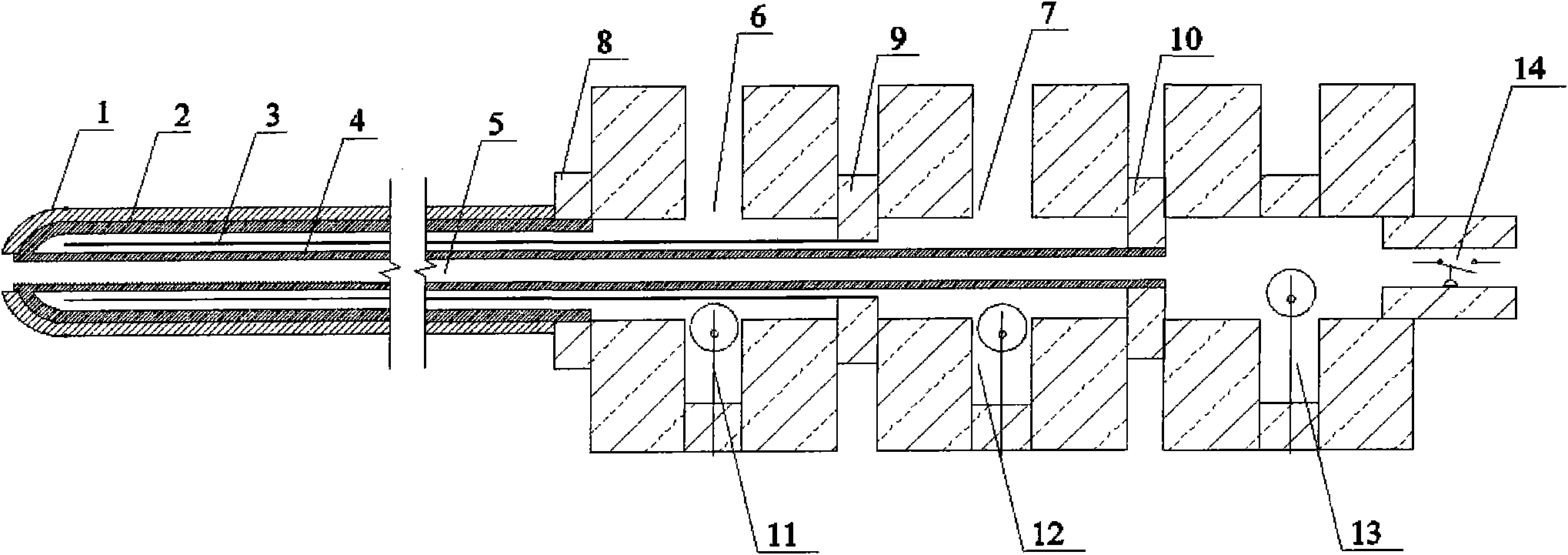
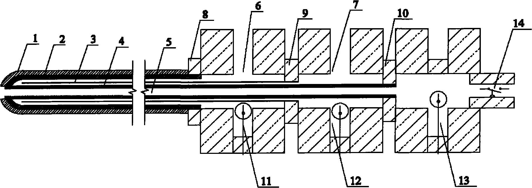
[0019] see figure 1 , an enthalpy probe probe for thermal plasma diagnosis, including a copper outer tube 2 with a wall thickness of 0.5mm, a stainless steel inlet and outlet water separation tube 3 with a wall thickness of 0.2mm, and a copper inner tube with a wall thickness of 0.3mm 4 and the first, second, and third bases 8, 9, and 10, the first, second, and third bases 8, 9, and 10 are all simplified characters, and the head and tail are sealed and welded together, and the front end of the outer tube 2 is hemispherical, and It is sealed and welded with the front end of the inner pipe 4. The inlet and outlet water separation pipe 3 is located between the inner and outer pipes. There is a gap of 4 mm between the inlet and outlet water separation pipe 3 and the outer pipe 2 to form a water inlet channel. There is a gap with the inner pipe 4 and forms a water outlet channel; the ends of the outer pipe 2, the inlet and outlet water separation pipe 3 and the inner pipe 4 are res...


PUM


Abstract

The invention discloses an enthalpy probe for diagnosing a thermal plasma, which comprises an outer tube, a water in and water out separation tube, an inner tube and a first base, a second base and a third base, wherein the first base, the second base and the third base are all cylinders and hermetically welded together end to end, and the water in and water out separation tube is located between the inner tube and the outer tube and respectively provided with gaps with the inner tube and the outer tube to respectively form a water inlet passage and a water outlet passage; the ends of the outer tube, the water in and water out separation tube and the inner tube are respectively hermetically welded on the inner walls of the first base, the second base and the third base, and the inner tube is communicated with the third base to form an air pumping and sampling passage; the lateral walls of the first base and the second base are respectively provided with a water inlet and a water outlet, and the water inlet passage and the water outlet passage are respectively provided with a water inlet temperature measurement platinum resistor and a water outlet temperature measurement platinum resistor; an air pumping and sampling temperature measurement platinum resistor is arranged inside the third base; and a corundum outer cover is arranged outside the outer tube, and the end of the corundum outer cover is hemispherical. The invention is easy and simple to handle and convenient to disassemble, poor working conditions and high temperature resistance property are considered both in the material selection and the design, and the interference on the plasma can be reduced during the measurement.

Description

technical field [0001] The invention relates to a key component of an enthalpy probe used for thermal plasma diagnosis, which is a contact measuring device capable of diagnosing the enthalpy value, temperature, velocity, and gas components of thermal plasma, and specifically relates to a high-temperature-resistant and anti-interference enthalpy probe probe probe. Background technique [0002] With the continuous development of the application of thermal plasma in the fields of hazardous waste treatment and chemical industry, the working characteristics of thermal plasma have attracted much attention. Due to the limitations of thermal plasma diagnostic techniques, work on fundamental research has lagged behind. [0003] The temperature of thermal plasma is between 2,000-20,000K, which is much higher than the measurement range of traditional thermocouple and thermal resistance. Also because of this, traditional velocimeters (such as non-water-cooled Pitot tubes) cannot be us...

Claims


Application Information

Patent Timeline
IPC IPC(8): G01D3/028G01D11/00
Inventor 赵鹏孟月东匡靖安刘卫倪国华
Owner INST OF PLASMA PHYSICS CHINESE ACAD OF SCI
Why Eureka
Try Eureka