
Buffer plate and manufacturing method thereof

A technology of buffer plate and weight ratio, which is applied in the field of buffer plate for dumpers and its manufacturing, to achieve the effect of reasonable structure, strong compression resistance and tear resistance, and reduced damage

Inactive Publication Date: 2012-01-25
BEIJING ZHONGTONG RILONG VEHICLE EQUIP TECH
View PDF0 Cites 0 Cited by
  • Summary
  • Abstract
  • Description
  • Claims
  • Application Information

AI Technical Summary

Problems solved by technology

Elastic buffer devices shall be installed on the towing beams'; Article 4.4.3' During the dumping process of the dumper conforming to the regulations of TB / T1335, the total inward bending moment value given to the side wall column on one side of the vehicle shall not be greater than 235kN.m , all uprights should bear the load evenly'. In order to reduce the damage and deformation of railway vehicles and ensure the safety of railway vehicles, the relevant manufacturers have tried their best to find a solution, but no applicable design has been developed for a long time, and the general The product cannot solve the above problems, which is obviously a problem that the relevant industry is eager to solve

Method used

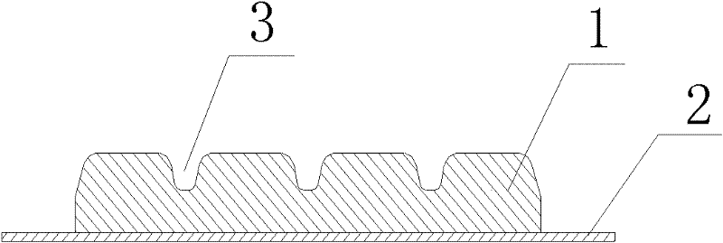
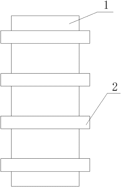
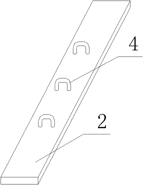

Image

  • Buffer plate and manufacturing method thereof
  • Buffer plate and manufacturing method thereof
  • Buffer plate and manufacturing method thereof

Examples


Embodiment 1

[0051] The buffer plate is prepared from the following components: 16000g of natural rubber; 1120g of active agent; 352g of peptizer; 320g of vulcanizing agent (S); 192g of accelerator; 320g of polyethylene glycol; Flow dispersant 880g; anti-aging agent 480g; anti-scorch agent 32g. Wherein the accelerator is preferably selected from accelerator NOBS and accelerator DM. In this embodiment, the accelerator consists of 160g of accelerator NOBS and 32g of accelerator DM. The active agent is zinc oxide or a combination of zinc oxide and stearic acid. The active agent in this example consisted of 800 g of zinc oxide and 320 g of stearic acid. The reinforcing filler is composed of high wear-resistant carbon black, semi-reinforcing carbon black and white carbon black in a weight ratio of 4.8-6.8:1-3:0.7-2.5. In this embodiment, the weight ratio of high wear-resistant carbon black, semi-reinforcing carbon black and white carbon black is 5.8:2:1.5. The anti-aging agent can be selecte...

Embodiment 2

[0053] The difference between this embodiment and the embodiments lies in that the proportioning ratio of each component is different. Among them, 9000g of natural rubber; 300g of active agent; 50g of peptizer; 120g of vulcanizing agent (S); 80g of accelerator; 6000g of reinforcing filler; The active agent is zinc oxide. The reinforcing filler is composed of high wear-resistant carbon black, semi-reinforcing carbon black and white carbon black in a weight ratio of 5.2:1.5:2. The accelerator is the accelerator NOBS. Dispersant AT-C is selected as the mobile dispersant.

Embodiment 3

[0055] The difference between this embodiment and the embodiments lies in that the proportioning ratio of each component is different. Among them, 11000g of natural rubber; 800g of active agent; 300g of peptizer; 270g of vulcanizing agent (S); 200g of accelerator; 9000g of reinforcing filler; The active agent is zinc oxide. The reinforcing filler is composed of high wear-resistant carbon black, semi-reinforcing carbon black and white carbon black in a weight ratio of 5.2:1.5:2. The accelerator is accelerator DM. Flow dispersant is selected flow agent AT-42.

[0056] Table 1 below shows the parameters of the above three embodiments.

[0057] Table 1

[0058]

[0059] The buffer plate of the present invention requires the following parameters:

[0060] Hardness (Shore A): 70~85

[0061] Tensile strength: (Mpa)≥5

[0062] Tear strength: kN / m: ≥25

[0063] Compression permanent change (70℃ / 24h, compression 25%): ≤50%

[0064] As can be seen from Table 1, the buffer pl...


PUM

PropertyMeasurementUnit
tensile strengthaaaaaaaaaa
hardnessaaaaaaaaaa

Abstract

The invention discloses a buffer plate and a manufacturing method thereof, wherein the buffer plate comprises the following compositions in parts by weight: 90 to 110 parts of natural rubber, 3 to 8 parts of active agent, 0.5 to 3 parts of peptizer, 1.2 to 2.7 parts of vulcanizing agent, 0.8 to 2 parts of accelerating agent, 0 to 2 parts of polyethylene glycol, 60 to 90 parts of reinforcing filler, 5 to 10 parts of machine oil, 2 to 6 parts of flow dispersant, 1 to 5 parts of anti-aging agent, and 0 to 1 part of scorch retarder. The buffer plate of the invention has the advantages of advancedand optimized formula, reasonable structure, strong compressive resistance and tear resistance, proper hardness, and good flexibility, can effectively reduce the damages on railway vehicles, and alsoease the impact force borne by a car dumper.

Description

technical field [0001] The invention relates to the technical field of dumper components, in particular to a buffer plate for a dumper and a manufacturing method thereof. Background technique [0002] The dumper is the first key equipment for bulk raw materials entering the factory in the production of enterprises, and it is also a large-scale mechanical equipment to improve the unloading efficiency of railway freight cars. The working method is as follows: the railway freight car loaded with bulk cargo enters the dumper body, presses the upper beam of the railway vehicle through the pressing beam of the dumper, and at the same time supports the side column of the railway vehicle with the support plate of the dumper, so that the dumper and the railway vehicle are synchronized at 160 degrees The overturning will unload the bulk cargo into the silo. When a dumper is used to dump and unload railway vehicles, the upper side beams and side columns of the railway vehicle are in r...

Claims


Application Information

Patent Timeline
Patent Type & Authority Patents(China)
IPC IPC(8): C08L7/00C08K13/02B65G67/48
Inventor 李凤金
Owner BEIJING ZHONGTONG RILONG VEHICLE EQUIP TECH
Learn More