
Thermal-radiating material and fire-resisting material using same

A technology of refractory materials and heat radiation, applied in the field of refractory materials, can solve the problems of short life (the coating will not work after only a few months, the coating is easy to age, the furnace radiation is strengthened and the heating is weakened, etc., and the heat loss can be reduced. , Improve thermal efficiency, improve the effect of high emissivity

Inactive Publication Date: 2011-02-16
BEIJING ENJI ENERGY SAVER TECH
View PDF7 Cites 13 Cited by
  • Summary
  • Abstract
  • Description
  • Claims
  • Application Information

AI Technical Summary

Problems solved by technology

However, the existing black body components begin to pulverize, fall off and be damaged after a period of use at high temperatures. Solve the problem at the root, and have a short lifespan (the coating will not work after only a few months), so that the radiation enhanced heating of the entire furnace is weakened

Method used


Image

  • Thermal-radiating material and fire-resisting material using same
  • Thermal-radiating material and fire-resisting material using same
  • Thermal-radiating material and fire-resisting material using same

Examples


Embodiment 1

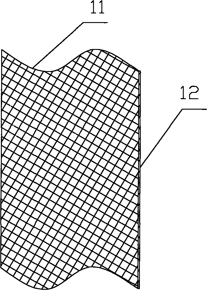
[0098] The furnace heat radiation element 21 can be arranged on the refractory material in the furnace, such as refractory bricks, and the shape of the furnace heat radiation element can be eight-sided cone, six-sided cone, cone, cone or cylinder. Alternatively, the structure of the furnace heat radiation element adopts the form of a cavity, that is, an octagonal cone, a hexagonal cone, a cone or a cylindrical cavity is arranged inside the body of the refractory brick.

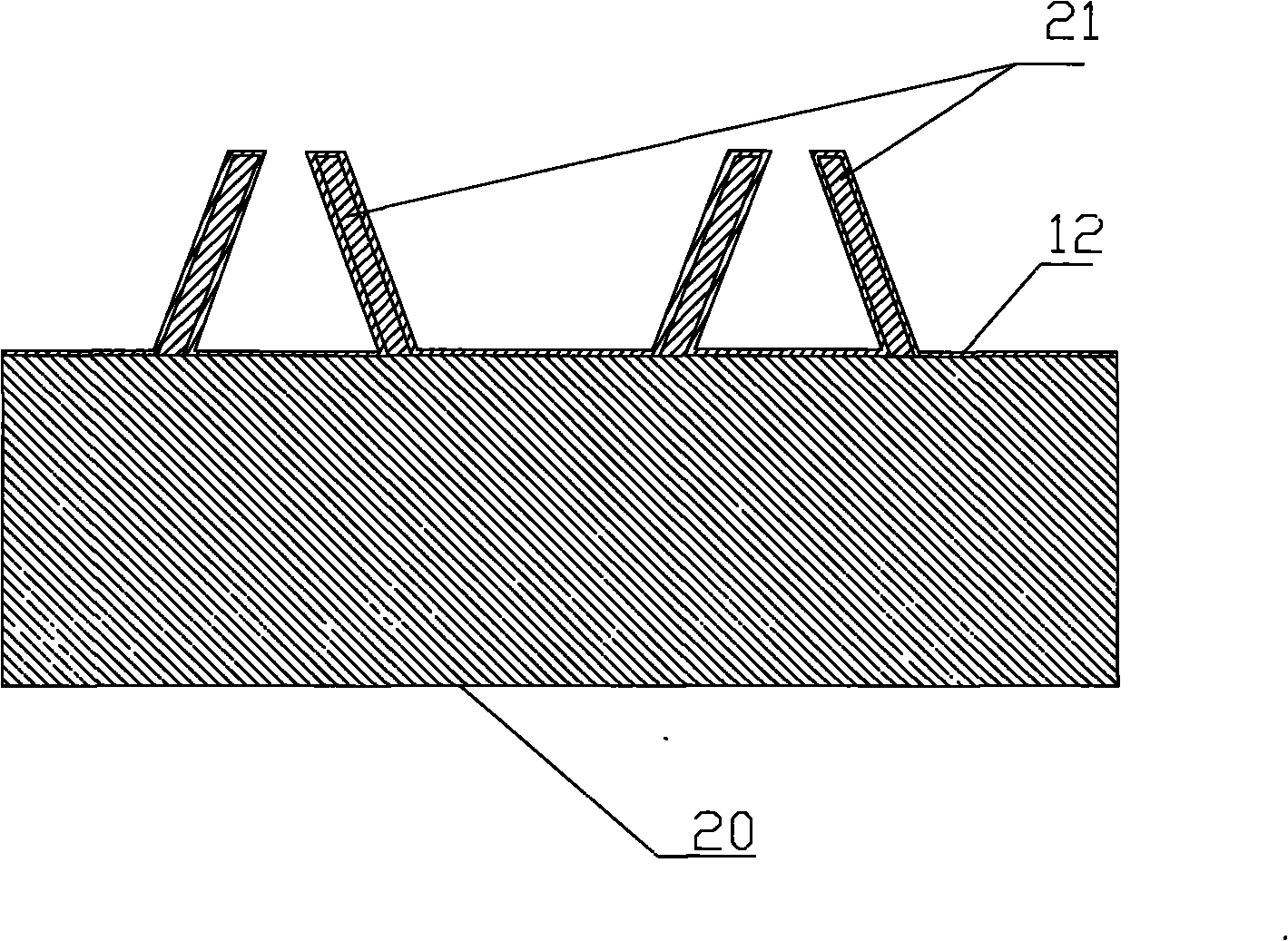
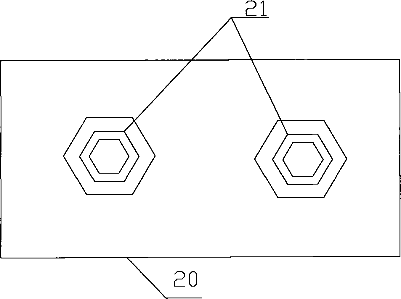
[0099] like figure 2 and 3 As shown, the furnace heat radiation element 21 adopts a hollow hexagonal pyramid structure, and the furnace heat radiation element 21 is arranged on the upper plane of the refractory brick 20 . The furnace heat radiation element 21 is surrounded by six side walls, and a bottom surface may also be provided at the bottom of the furnace heat radiation element 21 . The furnace heat radiation element 11 has an inner wall and an outer wall, which can effectively increase the heat trans...

Embodiment 2

[0104] The heat radiation material 12 is coated on the inner surface of the furnace heat radiation element 31, and the thermal emissivity of the heat radiation material 12 is 0.95, and the heat radiation material 12 is fixed on the inner wall of the furnace or the inner wall of the furnace heat radiation element 31 by special bonding technology The heat radiation material 12 can be sprayed with multiple layers on the entire inner wall of the furnace and the inner wall of the heat radiation element 31 of the furnace.

[0105] For the structural form of the furnace heat radiation element 21 and the furnace heat radiation element 41 of the preferred embodiment 1 and the preferred embodiment 2, it has a high heat emissivity in the normal direction, and the inner walls of the furnace heat radiation elements 21 and 41 absorb the diffuse heat in the furnace. At the same time, it continuously emits heat rays with the same high emissivity, and directly shoots to the heated object. In th...


PUM


Abstract

The invention discloses a fire-resisting material using a thermal-radiating material, comprising a fire-resisting material body, wherein a furnace thermal-radiating element is arranged on the fire-resisting material body, and the thermal-radiating material is coated on the outer surfaces of the fire-resisting material body and the furnace thermal-radiating element. The invention also discloses a thermal-radiating material. Aiming at the defects of various traditional industrial heating furnaces, the thermal-radiating material is sprayed and arranged on the inner wall of a furnace to reduce the thermal loss of an industrial heating stove, thereby increasing heat efficiency and achievingthe purposes of saving energy and reducing emission.

Description

technical field [0001] The invention relates to a thermal energy technology, in particular to a heat radiation material and a refractory material using the heat radiation material. Background technique [0002] It can be seen from the currently used industrial heating furnaces that in order to increase the heat obtained by the workpiece, the heat transfer in the furnace must be increased, so it is necessary to increase the emissivity of the furnace wall and increase the heat transfer area in the furnace. Most of the existing industrial heating furnace walls are refractory bricks, castables or refractory fibers, which have low emissivity, high energy consumption, and low heating efficiency. [0003] The basic theory of heat transfer includes the following points: [0004] A) The form of heat energy transfer: radiation, conduction, convection. [0005] B) Stephen-Boltzmann law: E=ε 0 C 0 (T / 100) 4 , the radiation intensity E is proportional to the fourth power of the temp...

Claims


Application Information

Patent Timeline
IPC IPC(8): C04B35/66C09K5/14
CPCY02P20/10
Inventor 李余庆
Owner BEIJING ENJI ENERGY SAVER TECH
Learn More