
Heat supply system and method

A heating system and heat storage technology, which is applied to heating systems, solar heating systems, and central heating, and can solve problems such as large power consumption, power consumption, and large investment in equipment

Inactive Publication Date: 2011-01-05
苏庆泉
View PDF0 Cites 4 Cited by
  • Summary
  • Abstract
  • Description
  • Claims
  • Application Information

AI Technical Summary

Problems solved by technology

The disadvantage of the existing solar heating system is that it depends too much on the weather. When the solar irradiance is low in rainy weather, the heat storage temperature of the hot water tank cannot reach the heating temperature required by the user, so it must be With auxiliary heating system
Usually, the auxiliary heating system adopts electric heating, and its highest energy efficiency ratio can only be close to 1. Even if there is still a certain solar irradiance on the solar collector plate during work, the solar heat cannot be effectively used for auxiliary heating, so Larger power consumption throughout the year and lower energy efficiency
In addition, since the temperature of the refrigerant must be higher than the heating temperature of the user, the working temperature of the solar collector is relatively high (usually above 42°C), so there is a large temperature difference with the environment, resulting in radiation, convection and Increased conduction heat loss reduces heat collection efficiency
At the same time, the solar heating system has a delivery pump. In order to maintain the circulation of the antifreeze, the delivery pump must consume a certain amount of electric energy
[0005] There is also a ground source heat pump circulation system that uses geothermal heat as a heat source. Since the ground source heat pump system needs to drill wells, the equipment investment is large, and the construction is complicated, and it is also easily restricted by geographical conditions.

Method used

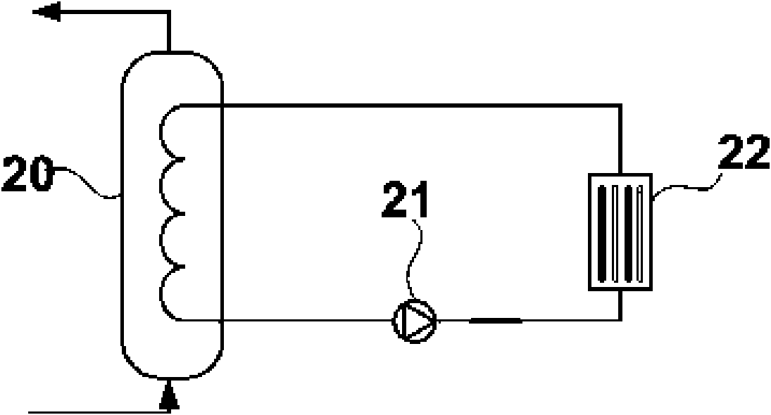

Image

  • Heat supply system and method
  • Heat supply system and method
  • Heat supply system and method

Examples


Embodiment Construction

[0023] In order to further explain the technical means and effects of the present invention to achieve the intended purpose of the invention, the specific implementation, structure, Features and their functions are described in detail below.

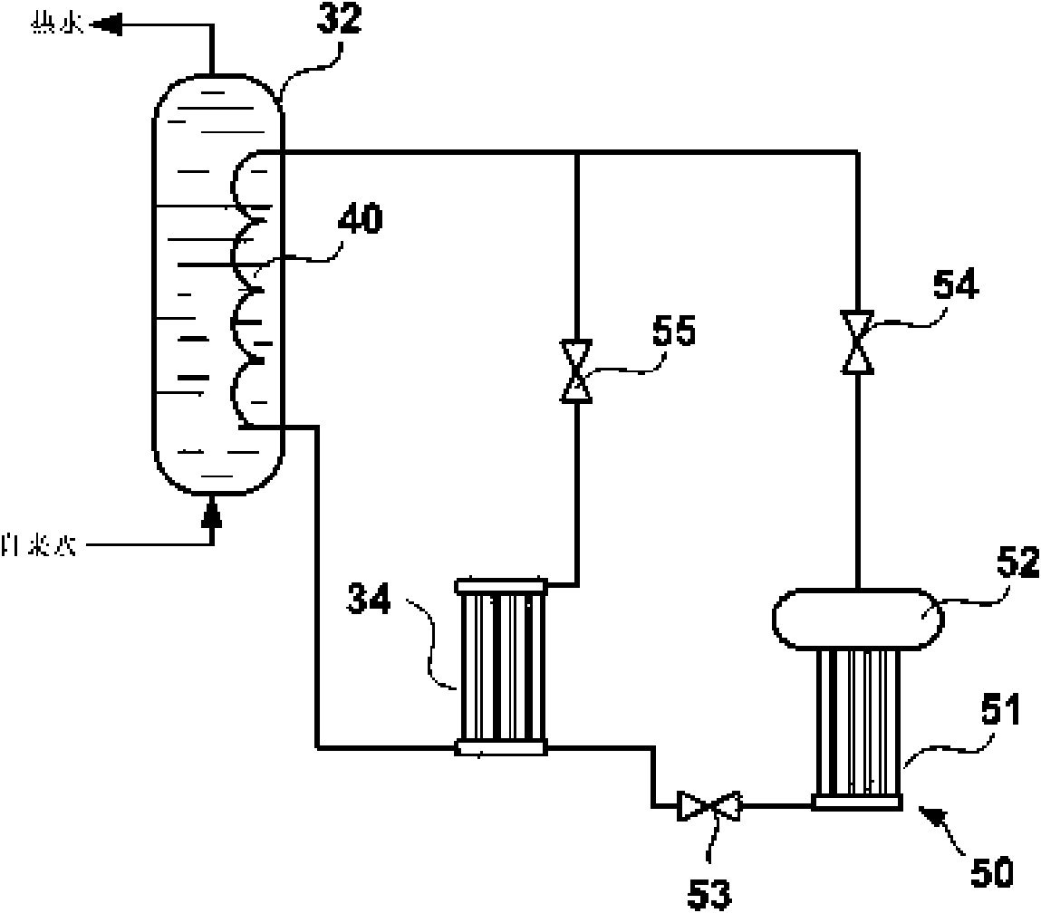
[0024] see image 3Shown is the heating system of Embodiment 1 of the present invention, including an energy storage tank 32 , a main solar heat collector 34 and a high-pressure heat storage device 50 . The energy storage tank 32 is provided with an energy storage heat exchange coil 40 , and the energy storage heat exchange coil 40 is connected with the main solar heat collector 34 through pipes to form a circulation loop in which the refrigerant circulates. The energy storage box 32 is filled with a heat storage agent with a phase transition temperature of 0-40°C. The heat storage agent is a latent heat storage agent, which can be water, lithium nitrate hydrate, calcium chloride hydrate, disodium hydrogen phosphate hydrate, sodium sul...


PUM


Abstract

The invention relates to heat supply system and method. The system comprises an energy storage box and a main solar heat collector, an energy storage heat exchange coiler in the energy storage box and the main solar heat collector form a circulation loop through a pipeline, and refrigerant circulates in the loop. The system is characterized by further comprising a high pressure heat accumulator consisting of an auxiliary solar heat collector and an accumulator, and the auxiliary solar heat collector is connected with the main solar heat collector to form a communication structure; and the accumulator is used for accommodating refrigerant gas generated in the auxiliary solar heat collector and is connected with an inlet pipeline of the heat storage heat exchange coiler. The system further comprises a hot water tank and a compression type heat pump subsystem composed of a condenser, a compressor and a throttling valve which are arranged in the hot water tank as well as an evaporator arranged in the energy storage tank. By means of the high pressure heat accumulator, the heat supply system can convert solar heat into driving force for the circulation of the refrigerant and realizes forced refrigerant circulation without power consumption, thereby being more energy-saving and environmental-friendly.

Description

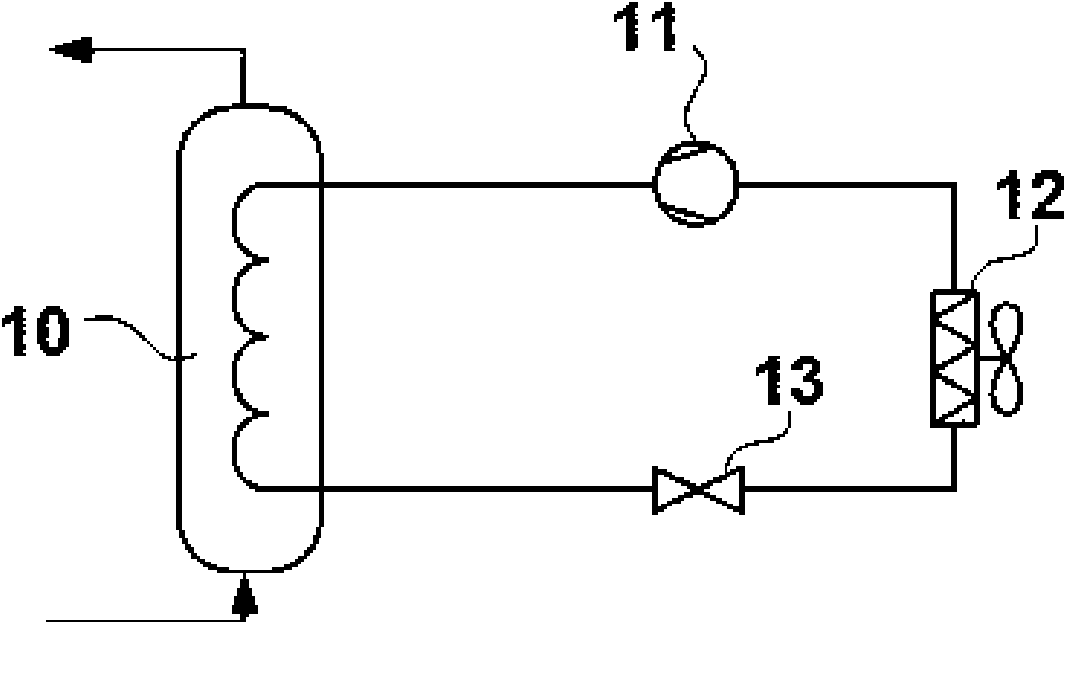
technical field [0001] The invention relates to a heating technology in the field of thermal engineering, in particular to a solar heating system and a heating method with a refrigerant-driven structure. Background technique [0002] The existing heating system mainly includes: fuel combustion heating system, electric heating heating system, air source heat pump system, solar energy heating system and ground source heat pump system. Among them, the primary energy efficiency of the fuel combustion heating system and the electric heating heating system is low, and it is difficult to meet the current social needs of energy conservation and emission reduction. [0003] see figure 1 Shown is an existing compressed air source heat pump heating system, which includes: a condenser 10, a compressor 11, an air source heat exchanger 12 and a throttle valve 13, and the above-mentioned components are connected by pipelines to form a closed cycle circuit, the refrigerant circulates in t...

Claims


Application Information

Patent Timeline
Patent Type & Authority Applications(China)
IPC IPC(8): F24D17/02F24D11/02F24J2/30F24S10/30
CPCY02B30/126Y02B10/70Y02E10/44
Inventor 苏庆泉
Owner 苏庆泉
Learn More