
A Heat Pipe Vapor Compression Composite Refrigeration System with Ejector for Air Conditioning

A refrigeration system and vapor compression technology, applied in air conditioning systems, household heating, heating methods, etc., can solve the problems of increasing the risk of refrigerant leakage, limited refrigerant driving force, failure of natural cooling methods, etc., and achieve good energy saving effect, clear pertinence, effect of good applicability

Active Publication Date: 2018-04-17
XI AN JIAOTONG UNIV
View PDF7 Cites 0 Cited by
  • Summary
  • Abstract
  • Description
  • Claims
  • Application Information

AI Technical Summary

Problems solved by technology

However, when the separated gravity heat pipe is arranged in this system, the position of the condenser must be higher than that of the evaporator, and the refrigerant driving force of the separated gravity heat pipe is limited. In some cases, the refrigerant of the heat pipe circuit is difficult to rely on gravity Natural circulation, resulting in the failure of the natural cooling method
In order to overcome the above disadvantages, there is a proposal to use a refrigerant liquid pump to drive forced circulation in the heat pipe circuit, and to a certain extent, the problem of refrigerant circulation in the system
However, the use of additional auxiliary refrigerant liquid pumps will also increase the risk of refrigerant leakage in the entire system, and the cost of the system will also increase significantly

Method used


Image

  • A Heat Pipe Vapor Compression Composite Refrigeration System with Ejector for Air Conditioning
  • A Heat Pipe Vapor Compression Composite Refrigeration System with Ejector for Air Conditioning
  • A Heat Pipe Vapor Compression Composite Refrigeration System with Ejector for Air Conditioning

Examples


Embodiment Construction

[0023] The present invention will be described in further detail below in conjunction with the accompanying drawings and specific embodiments.

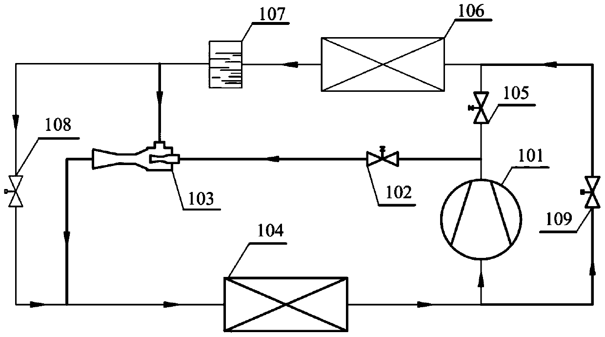
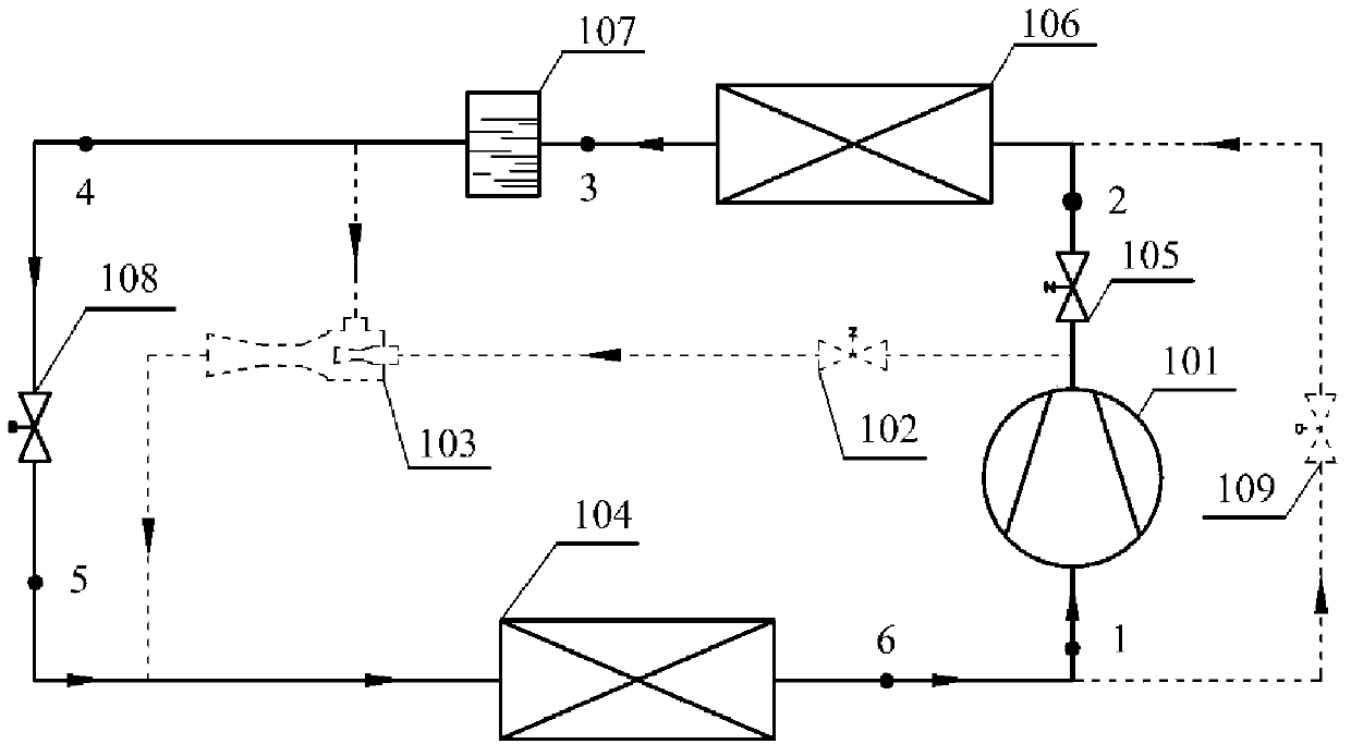
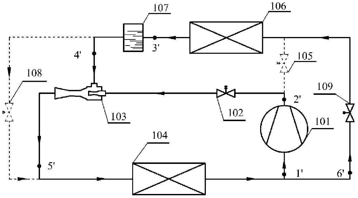
[0024] Such as figure 1 As shown, in this embodiment, a heat pipe vapor compression compound refrigeration system for air conditioning with an ejector is used. The outlet of the frequency conversion compressor 101 is divided into two paths, and one path is connected to the nozzle inlet of the ejector 103 after passing through the first flow regulating valve 102. The outlet of the ejector 103 is connected with the inlet of the evaporator 104; the other path is connected with the inlet of the condenser 106 after the solenoid valve 105, and the outlet of the condenser 106 is connected with the inlet of the liquid storage device 107, and the outlet of the liquid storage device 107 is divided into two One way is connected to the inlet of the evaporator 104 after passing through the electronic expansion valve 108, and the other is connected...


PUM


Abstract

A heat pipe vapor compression compound refrigeration system for air conditioners with an ejector. The outlet of the frequency conversion compressor is divided into two channels. After passing through the solenoid valve, it is connected to the inlet of the condenser, and the outlet of the condenser is connected to the inlet of the liquid receiver. The outlet of the liquid receiver is divided into two routes, one is connected to the inlet of the evaporator after passing through the electronic expansion valve, and the other is connected to the ejector inlet. The outlet of the evaporator is divided into two routes, one of which is connected to the inlet of the variable frequency compressor; the other is connected to the inlet of the condenser after passing through the flow regulating valve; the system includes two working modes: compression refrigeration mode and heat pipe cooling mode; Under the conditions of the equipment, the forced circulation of the refrigerant in the heat pipe circuit under the heat pipe cooling mode is realized, which ensures the reliability of cooling by using the outdoor natural cold source, and plays a positive role in promoting the development of data center / communication base station (or computer room) air conditioning energy-saving technology. .

Description

technical field [0001] The invention belongs to the technical field of air conditioning, and in particular relates to a heat pipe vapor compression composite refrigeration system for air conditioning with an ejector used for data center / communication base station (or machine room) air conditioning. Background technique [0002] In recent years, the rapid growth of my country's data centers and communication base stations has brought about a sharp increase in energy consumption of data centers and communication base stations, which poses challenges to the continuous innovation of data center cooling technology and the improvement of cooling energy efficiency. Due to the high heat generation density of data centers / communication base stations (or computer rooms), air conditioners are used to cool down in summer and winter to ensure their safe and reliable operation, which also greatly increases the energy consumption of air conditioners. Therefore, how to effectively reduce th...

Claims


Application Information

Patent Timeline
Patent Type & Authority Patents(China)
IPC IPC(8): F24F5/00
CPCF24F5/001F24F5/0046
Inventor 鱼剑琳李云翔晏刚白涛
Owner XI AN JIAOTONG UNIV
Learn More