
Systems and methods for beacon integrated with displays

a technology of systems and methods, applied in the field of systems and methods for beacons integrated with displays, can solve the problems of inability to distinguish one user from multiple users, inability to detect and record user smart phone mac addresses, and inability to detect and record user positions of wireless access points

Inactive Publication Date: 2019-05-02
SENTRY CENTS HLDG LLC
View PDF3 Cites 56 Cited by
  • Summary
  • Abstract
  • Description
  • Claims
  • Application Information

AI Technical Summary

Benefits of technology

The patent text describes a solution that uses indoor positioning technology to help shoppers find items in retail stores and track store employees and assets. This data can be used to improve customer engagement and optimize floor plans for better efficiency. The solution also includes a technique called virtual beaconing, which allows multiple companies to use one collection of beacons as if they were their own. This approach provides reliability and refined positioning, as well as automatic management of locations and the ability to virtualize beacons through a lighting platform. Overall, this technology can help save money for building owners and operators by optimizing floor plans and increasing energy savings.

Problems solved by technology

For example, the use of occupancy sensors, including PIR and / or Ultrasonic sensors may be unable to differentiate one user from multiple users.
Cameras, such as security cameras, are expensive and intrusive, especially when used in an office setting.
Wi-Fi tracking, where wireless access points detect and record user smart phone MAC addresses lack in user position accuracy, especially when installed in locations with numerous partitions, walls, and levels, such as offices, hospitals, universities, and similar venues.
Common with all these technologies is their inability to bring any value or usefulness to the user, rather they are strictly employed for user tracking and / or as an input into a building management system, such as an occupancy sensor for lighting or HVAC.

Method used


Image

  • Systems and methods for beacon integrated with displays
  • Systems and methods for beacon integrated with displays
  • Systems and methods for beacon integrated with displays

Examples


Embodiment Construction

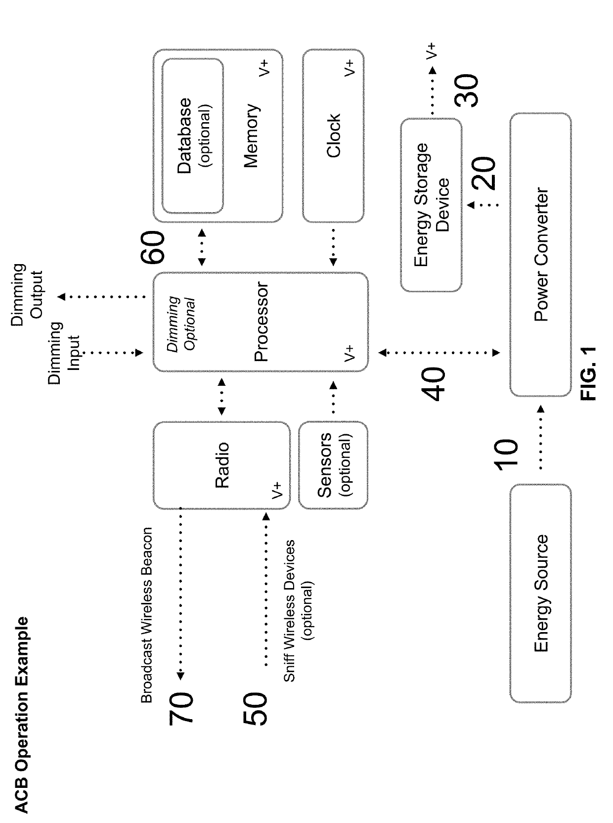
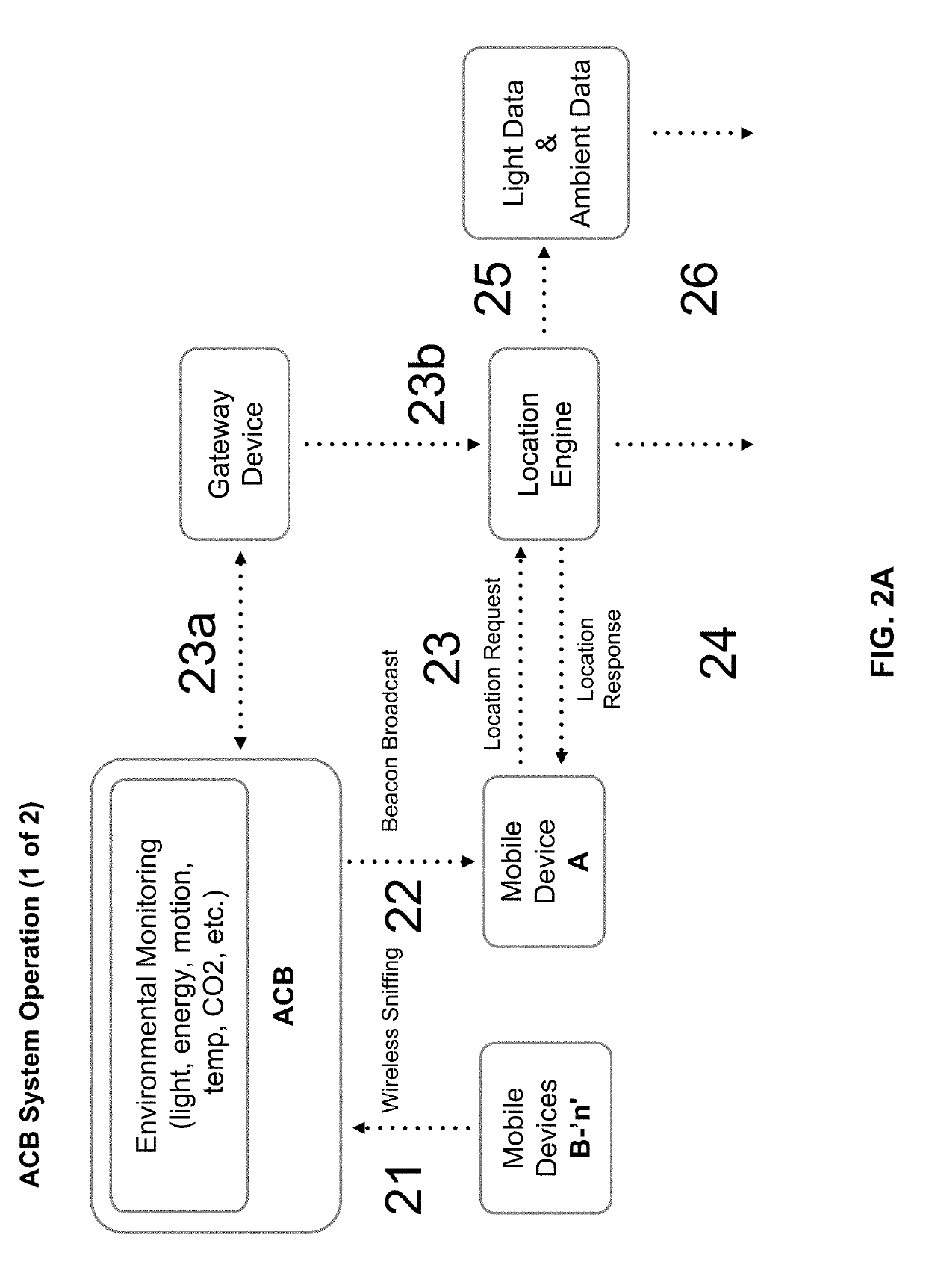
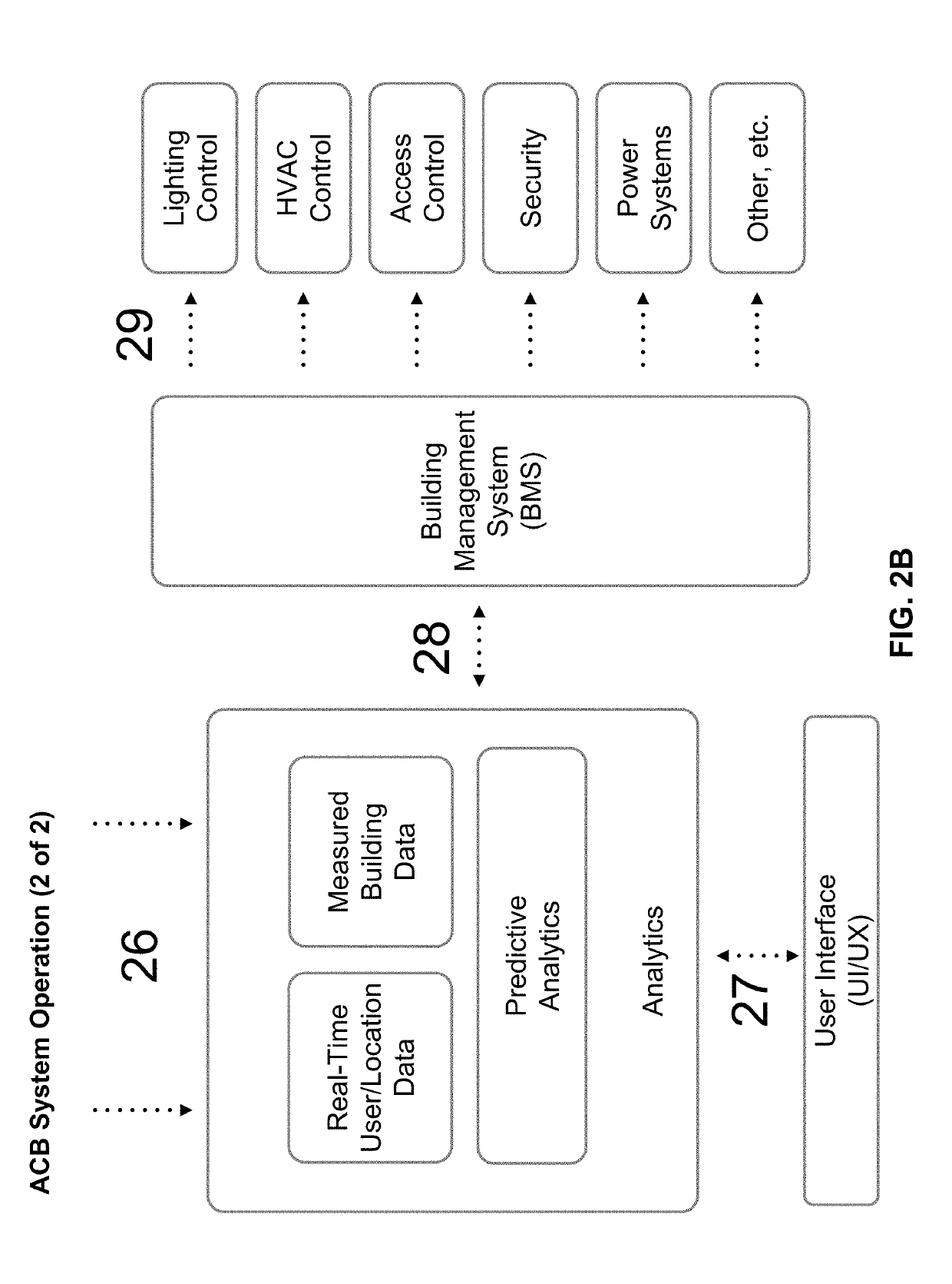
[0072]The present solution is directed to systems, methods, and apparatus for light enabled indoor positioning and reporting. In some embodiments, the present solution includes or uses an advanced control beacon (“ACB”). For example, an ACB (e.g., ACB 1135 illustrated in FIG. 11) can be an electronic device that is installed into or adjacent to one or more light fixtures, light bulbs, light engines, light panels, light housings, light displays, decorative light fixtures, multi-purpose lighting products, or similar such devices, collectively referred to as the Light Source. The ACB can also be installed into or adjacent to any hardware device such as an occupancy sensor, daylight sensor, furniture, kiosk, or similar devices also for purposes of this document referred to as the Light Source. The ACB can include electronic components installed within or adjacent to the Light Source. The Light Source can have any configuration, such as any lighting technology ranging from solid state, o...


PUM


Abstract

The present disclosure is directed systems, methods, and apparatus for light enabled indoor positioning and reporting. A server receives data including sensor data from each of a plurality of display devices established at a predetermined location of a plurality of predetermined locations. The server determines, from data of a first display device of the plurality of display devices, a first state of a first predetermined location of the plurality of predetermined locations. The server determines, from data of a second display device of the plurality of display devices, a second state of a second predetermined location of the plurality of predetermined locations. The server communicates, to one or more mobile devices, one of the first state of the first predetermined location or the second state of the second predetermined location.

Description

CROSS-REFERENCES TO RELATED APPLICATIONS[0001]This application claims the benefit of priority under 35 U.S.C. § 119 to U.S. Provisional Patent Application No. 62 / 578,171, filed Oct. 27, 2017, which is hereby incorporated by reference herein in its entirety.FIELD OF THE DISCLOSURE[0002]The present application is generally directed towards the use of wireless beacons, wireless sniffing, and lighting as a means of delivering both positioning for mobile devices as well as real-time and predictive feedback of building occupancy, enabling the contextual engagement of users and smarter buildings.BACKGROUND[0003]Humans spend 90% of our time indoors. However, using existing infrastructure to establish indoor positioning of people (users) may be unreliable or inaccurate.BRIEF SUMMARY OF THE DISCLOSURE[0004]The systems and methods of the present disclosure described herein address the need for contextually engaging users based on their location, measuring user traffic through a space, such as ...

Claims


Application Information

Patent Timeline
Patent Type & Authority Applications(United States)
IPC IPC(8): H04W64/00G06Q50/06G06Q10/04G06Q10/06G06F3/0484
CPCH04W64/003G06Q50/06G06Q10/04G06Q10/067G06F3/0484
Inventor ZAMPINI, II, THOMASVALOIS, CHARLESZAMPIERON, JEFFREY
Owner SENTRY CENTS HLDG LLC
Learn More