
Ring-shaped electro-plastic self-piercing riveting system

An electroplastic, self-piercing riveting technology, applied in the field of mechanical engineering, can solve the requirements of reducing the rigidity of equipment punching riveting ability and rivet strength, reducing the plastic deformation resistance of riveted advanced high-strength steel, and radial cracks at the bottom of the joint. The effect of reducing riveting force, improving connection quality and easy mechanical interlocking

Active Publication Date: 2012-11-21
SHANGHAI JIAO TONG UNIV
View PDF0 Cites 0 Cited by
  • Summary
  • Abstract
  • Description
  • Claims
  • Application Information

AI Technical Summary

Problems solved by technology

The present invention incorporates a ring-shaped electroplastic system on the basis of improving the existing technology, which solves the problem that radial cracks or even brittle cracks are likely to occur at the bottom of the joint when the above-mentioned alloy plate is riveted, and reduces the plastic deformation when riveting advanced high-strength steel Resistance, on the one hand, reduces the requirements for the punching riveting capacity of the equipment, the rigidity of the C-frame of the rivet gun, and the strength of the rivet, and reduces the production cost; Overall Connection Quality

Method used


Image

  • Ring-shaped electro-plastic self-piercing riveting system
  • Ring-shaped electro-plastic self-piercing riveting system
  • Ring-shaped electro-plastic self-piercing riveting system

Examples


Embodiment 1

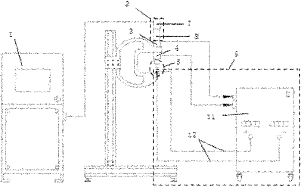
[0034] Such as figure 1 As shown, this embodiment includes: power and control cabinet 1, servo power system 2, displacement sensor 3, pressure sensor 4, riveting actuator 5 and ring electroplastic system 6, wherein: power and control cabinet 1 and servo power system 2-phase connection, the annular electroplastic system 6 is connected with the riveting actuator 5;

[0035] The servo power system 2 includes a servo motor 7 and a lead screw nut mechanism 8, the servo motor 7 is connected to the power and the control cabinet 1 to receive power and control cabinet control, and the output end of the servo motor 7 is connected to the lead screw and nut mechanism 8 to realize power delivery.

[0036] The displacement sensor 3 is connected in series under the screw nut mechanism 8 to convert the collected screw speed information into riveting speed information; the pressure sensor 4 is connected in series above the riveting actuator 5 to collect force feedback information from the mec...

Embodiment 2

[0056] The implementation conditions and process flow of this embodiment refer to Embodiment 1; the plates 18 to be connected in this embodiment are: aluminum alloy AA6061-T6+high-strength steel DP780, that is, the aluminum alloy is on the top, the high-strength steel is on the bottom, and the thickness of the plates matches: 2mm+1.4mm.

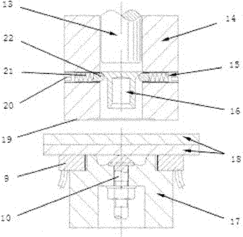
[0057] The semi-hollow rivet 16 in this embodiment adopts a traditional self-piercing riveting countersunk rivet with a head diameter of 7.8 mm, a leg outer diameter of 5.3 mm, and a rivet length of 7 mm. The material is boron-treated medium carbon steel.

[0058] Process parameters: the impact speed of the drive rod 13 is 120mm / min, the impact stroke is 7mm, and the current of the controllable DC power supply 11 is 600A.

[0059] Above-mentioned two embodiments have remarkable beneficial effect:

[0060] In the above embodiment, by applying current in the deformation direction of the material during the self-piercing riveting process, the m...


PUM

PropertyMeasurementUnit
yield strengthaaaaaaaaaa
widthaaaaaaaaaa
heightaaaaaaaaaa

Abstract

The invention relates to a ring-shaped electro-plastic self-piercing riveting system in the technical field of riveting, comprising a power and control cabinet, a servo power system, a displacement sensor, a pressure sensor, a riveting execution mechanism and a ring-shaped electro-plastic system, wherein the power and control cabinet supplies current power to the servo power system consisting of a servo motor and a lead screw nut mechanism, and meanwhile, provides the control signals of the motion displacement, speed, starting point, stopping point and the like to complete various preset riveting processes; the displacement sensor and the pressure sensor are connected between the servo power system and the riveting execution mechanism in series to collect corresponding real-time signals; and the ring-shaped electro-plastic system is connected with the riveting execution mechanism to supply controllable direct current for the electro-plastic effect. The invention solves the problem that the bottom of a joint is easy to crack radially and even embrittle when a brittle hard non-ferrous alloy plate is riveted, effectively reduces the plastic deformation resistance during the riveting of the advanced high-strength steel, and enhances the comprehensive connection quality of the joint.

Description

technical field [0001] The invention relates to a riveting device in the technical field of mechanical engineering, in particular to an annular electroplastic self-piercing riveting system. Background technique [0002] In recent years, with the dwindling oil resources and increasing environmental pollution, the lightweight of automobile bodies aimed at improving fuel economy and environmental performance has become the general trend of the development of the automobile industry. The application of non-ferrous alloy materials such as magnesium and aluminum and new lightweight materials such as advanced high-strength steel has naturally become an important means of lightweighting the body. However, non-ferrous alloy materials such as magnesium and aluminum have good thermal conductivity, high electrical conductivity, and are easy to alloy with copper. At the same time, the melting point and thermal expansion coefficient of the above-mentioned non-ferrous alloys and advanced h...

Claims


Application Information

Patent Timeline
Patent Type & Authority Patents(China)
IPC IPC(8): B21J15/10B21J15/16B21J15/38
CPCB21J15/025B21J15/08B21J15/36
Inventor 李永兵林忠钦来新民楼铭陈关龙
Owner SHANGHAI JIAO TONG UNIV
Learn More