
Low-concentration photovoltaic component

A photovoltaic module and concentrating system technology, applied in the field of solar photovoltaic power generation, can solve the problems of rising operating temperature of series resistance loss devices, decrease of open circuit voltage and conversion efficiency, increase of series resistance loss, etc., so as to reduce heat dissipation difficulty and heat dissipation. device cost, high battery conversion efficiency, the effect of reducing the total cost

Inactive Publication Date: 2010-11-10
普尼太阳能(杭州)有限公司
View PDF4 Cites 3 Cited by
  • Summary
  • Abstract
  • Description
  • Claims
  • Application Information

AI Technical Summary

Problems solved by technology

[0008] (2) The unevenness of light intensity distribution on the surface of the battery increases
In the case of a certain concentration rate, the uneven distribution of light intensity will lead to uneven distribution of temperature and current on the surface of the battery, resulting in a decrease in open circuit voltage and conversion efficiency.
[0009] (3) The loss of series resistance increases
The increase of the concentration rate causes the increase of the current density, and the series resistance loss is proportional to the square of the current density, so the increase of the concentration rate causes the increase of the series resistance loss
In addition, the increase in the loss of series resistance will also cause the operating temperature of the device to increase, resulting in a decrease in conversion efficiency
[0010] Therefore, the existing public solar concentrating photovoltaic systems fail to achieve the goal of truly effectively reducing the total cost of system power generation through the optimal combination of battery chips, concentration ratios, solar tracking and cooling systems

Method used


Image

  • Low-concentration photovoltaic component
  • Low-concentration photovoltaic component
  • Low-concentration photovoltaic component

Examples


Embodiment 1

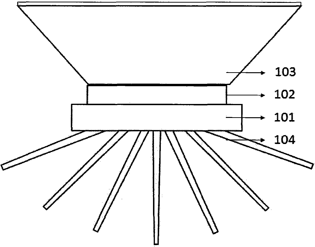
[0028] Such as figure 1 The low-magnification concentrating photovoltaic module shown includes a backplane 101 , a light receiver 102 , a concentrating system 103 and a heat sink 104 .

[0029]The backplane 101 is composed of an aluminum alloy substrate, epoxy resin doped with heat-conducting particles, and copper foil, wherein the copper foil is pasted on the aluminum alloy substrate through epoxy resin. Copper foil, epoxy resin, and aluminum alloy substrate are all good conductors of heat, which can conduct the heat on the copper foil to the aluminum alloy substrate in time, and conduct it to the radiator 104 connected to the base of the backplane 101 through the aluminum alloy substrate. The battery is cooled to prevent the conversion efficiency from decreasing or even causing accidents due to the high temperature of the photoreceiver during operation. The heat sink 104 is composed of a plurality of cooling fins.

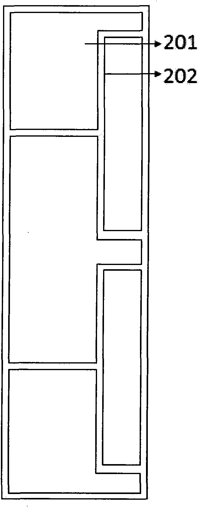
[0030] Such as figure 2 As shown, the copper foil inclu...

Embodiment 2

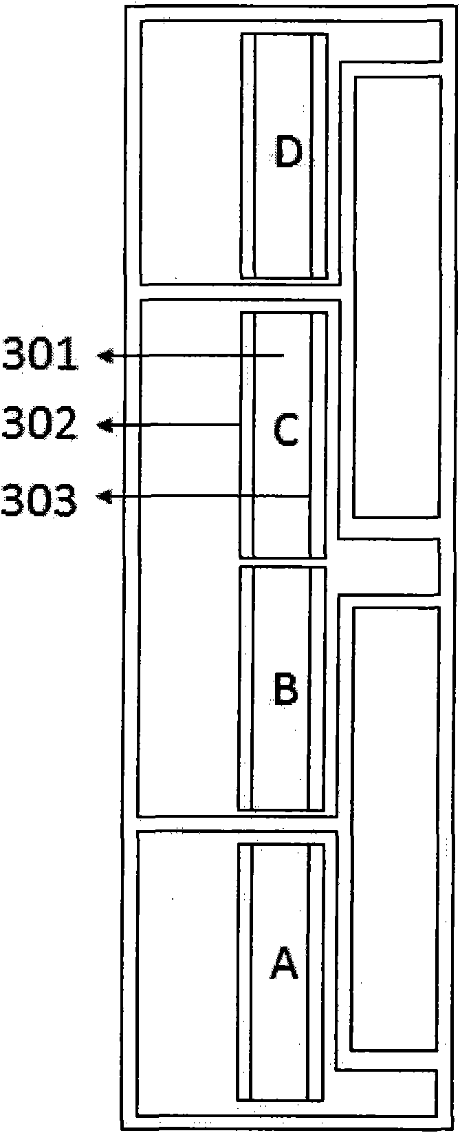
[0036] It is exactly the same as Embodiment 1, except that the positive and negative electrodes of the solar cell chips 301 (A, B, C, D) are set differently:

[0037] A: Left negative and right positive, B: Left positive and right negative, C: Left negative and right positive, D: Left positive and right negative, the effects are exactly the same.

[0038] Correspondingly, the connection methods between the solar cell chips 301 are also different: the negative electrode of A is connected to the copper foil area a, the positive electrode is connected to the copper foil area b; the negative electrode of B is connected to the copper foil b area, and the positive electrode is connected to the copper foil area b. Foil c-area connection; C’s negative pole is connected to copper foil c-area, positive pole is connected to copper foil d-area, D’s negative pole is connected to copper foil d-area, positive pole is connected to copper foil e-area...and so on, still forming a series connecti...


PUM

PropertyMeasurementUnit
Thicknessaaaaaaaaaa
Thicknessaaaaaaaaaa
Widthaaaaaaaaaa

Abstract

The invention discloses a low-concentration photovoltaic component. The photovoltaic component comprises a back panel, a light receiver and a concentrating system, wherein the back panel comprises a substrate and a metal foil; the surface of the metal foil is cut into a plurality of insulated periodic units; the substrate and the metal foil are adhered together through an insulating heat-conducting adhesive; the light receiver consists of serial solar cell chips of a plurality of linearly arranged glass substrates and is adhered in the periodic unit on the metal foil through the insulating heat-conducting adhesive; the adjacent solar cell chips are connected through the metal foil; and the concentrating light comprises a light focusing strip-shaped lens, a parabolic trough, a combined parabolic surface and an auxiliary element. By using the photovoltaic component, the sunshine can be focused on the light receiver with low cost and high efficiency under the optimal focusing condition so as to obtain the maximum photovoltaic conversion efficiency. The low-concentration photovoltaic component reduces the difficulty and the cost for heat dissipation and sun tracking while reducing the series resistance, the machining method for the component is simple and reliable, and the manufactured component has stable performance.

Description

technical field [0001] The invention belongs to the technical field of solar photovoltaic power generation, and in particular relates to a solar concentrated photovoltaic power generation system. Background technique [0002] Solar photovoltaic power generation technology is one of the inevitable ways to solve future energy problems, but the high cost of system power generation and shortage of raw materials are the main factors that limit the rapid popularization of this technology. Solar concentrating photovoltaic (CPV) technology uses a cheap concentrating system to concentrate sunlight to a small light receiver, thereby reducing the amount of expensive battery chips, which is a way to reduce the total cost of photovoltaic power generation systems. Effective Ways. [0003] A concentrated photovoltaic system usually consists of a concentrated system, a light receiver, a heat dissipation system and a backplane, and its core is a light receiver and a concentrated system. ...

Claims


Application Information

Patent Timeline
IPC IPC(8): H01L31/052H02N6/00H01L31/055
CPCY02E10/52Y02E10/50
Inventor 王东甄炯炯窦海林
Owner 普尼太阳能(杭州)有限公司
Learn More