
Three-way catalytic reactor protecting system for automobile

A catalytic reactor and protection system technology, applied in the field of automobile three-way catalytic reactor protection system, can solve the impact of three-way catalytic reactor purification effect, reduce the service life of three-way catalytic reactor, damage to three-way catalytic reactor, etc. problems, to achieve the effect of improving heat dissipation, reducing energy consumption, and reducing the difficulty of heat dissipation

Active Publication Date: 2013-06-05
ZHEJIANG GEELY AUTOMOBILE RES INST CO LTD +1
View PDF1 Cites 0 Cited by
  • Summary
  • Abstract
  • Description
  • Claims
  • Application Information

AI Technical Summary

Problems solved by technology

However, as a new type of clean and environmentally friendly compressed natural gas vehicle, the temperature of the exhaust gas emitted by the engine is very high, and ordinary vehicles will also emit high-temperature exhaust gas under high load and high speed conditions.
Existing automobiles do not have a cooling device to reduce the exhaust gas temperature, so the three-way catalytic reactor often works at an excessively high temperature. On the one hand, the catalytic activity of the catalyst in the three-way catalytic reactor is reduced, resulting in purification of the three-way catalytic reactor The effect is affected, so that more harmful gases are discharged into the air and cause environmental pollution; on the other hand, the high-temperature exhaust gas will also cause fatal damage to the three-way catalytic reactor, greatly reducing the service life of the three-way catalytic reactor

Method used


Image

  • Three-way catalytic reactor protecting system for automobile
  • Three-way catalytic reactor protecting system for automobile
  • Three-way catalytic reactor protecting system for automobile

Examples


Embodiment Construction

[0030] The following are specific embodiments of the present invention and in conjunction with the accompanying drawings, the technical solutions of the present invention are further described, but the present invention is not limited to these embodiments.

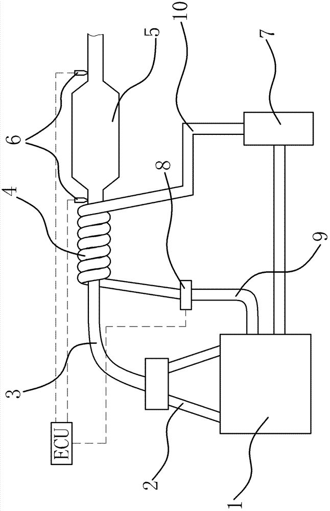
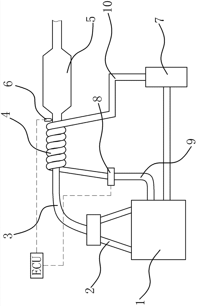
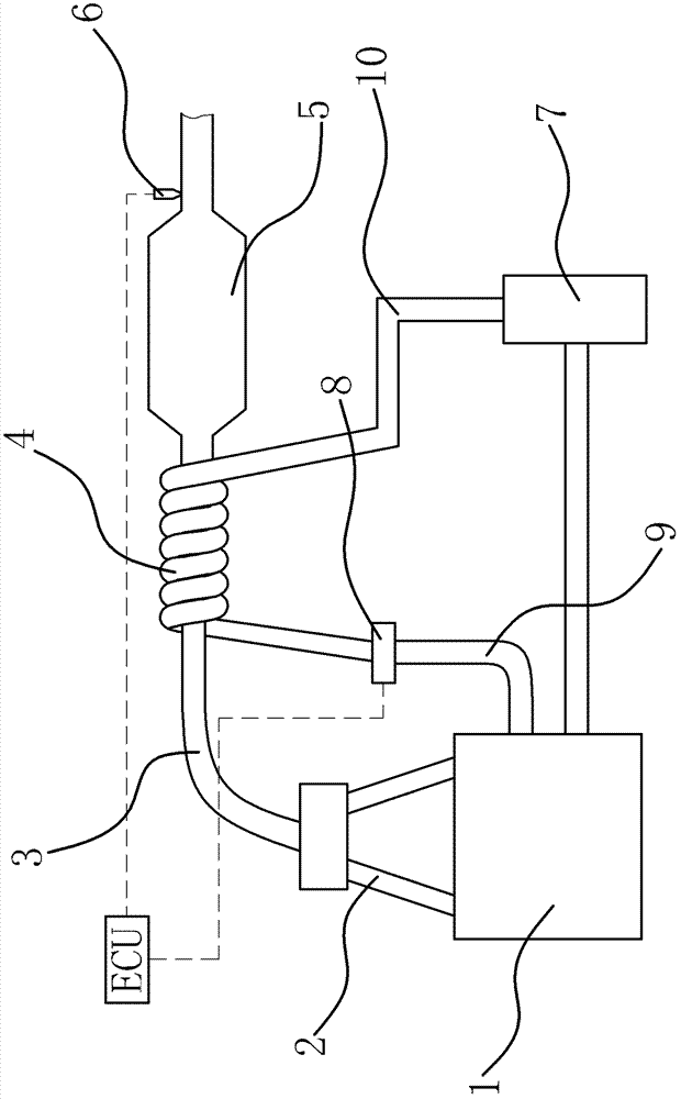
[0031] like figure 1 As shown, the automotive three-way catalytic reactor protection system includes ECU, sensing element, radiator 7 and other components, cooling device and control mechanism.

[0032]Specifically, the automobile includes an engine 1 , an exhaust pipe 3 communicating with the exhaust manifold 2 of the engine 1 and a three-way catalytic reactor 5 connected to the exhaust pipe 3 . In order to reduce the temperature of automobile exhaust, make the three-way catalytic reactor 5 work in the optimum temperature range, to achieve the best catalytic effect, and prevent the high-temperature exhaust gas from causing damage to the three-way catalytic reactor 5. The exhaust pipe 3 between the manifold 2 and the thre...


PUM


Abstract

The invention provides a three-way catalytic reactor protecting system for an automobile, which belongs to the technical field of vehicles. The technical problems of poor purification effect, short service life and the like of a traditional automobile three-way catalytic reactor are solved. In the three-way catalytic reactor protecting system for the automobile, a vehicle comprises an exhaust pipe and a three-way catalytic reactor, wherein the exhaust pipe is communicated with an engine exhaust manifold; the three-way catalytic reactor is connected to the exhaust pipe. The protecting system comprises an electrically controlled unit (ECU) and a sensing element which is arranged on the exhaust pipe and can detect tail gas temperature, wherein the sensing element is connected with the ECU. Acooling device capable of reducing the tail gas temperature in the exhaust pipe is arranged on the exhaust pipe between the exhaust manifold and the three-way catalytic reactor and is connected with the ECU through a control mechanism capable of controlling the cooling device to cool tail gas forcibly. By reducing the tail gas temperature, the three-way catalytic reactor can be effectively protected. At the same time, the three-way catalytic reactor protecting system for the automobile has the advantages of low energy consumption, high environmental friendliness and the like.

Description

technical field [0001] The invention belongs to the technical field of vehicles, and relates to a protective system for a three-way catalytic reactor of an automobile. Background technique [0002] As the most important means of transportation at present, automobiles not only bring a lot of convenience to people, but also are the main sources of energy consumption and pollutant emissions. According to the classified statistics of the sources of urban air pollutants, in the big cities of our country, about 80% of the pollutants come from automobile exhaust. A large amount of vehicle exhaust is concentrated in urban emissions, deteriorating the air quality in some big cities, and environmental protection is imminent. In order to cope with the increasingly serious problems of vehicle exhaust emissions and the increasing shortage of petroleum fuels, domestic and foreign auto companies are constantly exploring new alternative clean fuels. Among them, compressed natural gas (CNG)...

Claims


Application Information

Patent Timeline
Patent Type & Authority Patents(China)
IPC IPC(8): F01N9/00
CPCY02T10/47Y02T10/40
Inventor 陈海兰李涛袁爽沈源由毅赵福全
Owner ZHEJIANG GEELY AUTOMOBILE RES INST CO LTD
Learn More