
Fluorescent discharge lamp tube, and liquid crystal display device

A discharge lamp and fluorescent technology, which is applied to discharge lamps, gas discharge lamps, and parts of gas discharge lamps, etc., can solve the problems of the inability of electrons to emit light at the center and the discharge breakdown of the film layer, so as to achieve low consumption and reduce consumption. Electricity, the effect of improving illumination

Active Publication Date: 2010-10-20
北京千树万树互联网科技有限公司
View PDF3 Cites 7 Cited by
  • Summary
  • Abstract
  • Description
  • Claims
  • Application Information

AI Technical Summary

Problems solved by technology

The problem with LEDs is that although about half of the injected electrons contribute to light, the remaining half of the electrons cannot emit light in the light-emitting center, but are converted into heat.
The main problem of EL is that if high brightness is expected, the thin film layer will produce discharge breakdown
It is necessary to have a countermeasure against UV light desaturation irradiated to the fluorescent film, but there are no papers that quantitatively discuss the phenomenon of UV light saturation

Method used


Image

  • Fluorescent discharge lamp tube, and liquid crystal display device
  • Fluorescent discharge lamp tube, and liquid crystal display device
  • Fluorescent discharge lamp tube, and liquid crystal display device

Examples


Embodiment 1

[0158] A component of the electron source of the present invention is to coat the metal electrode with insulator particles at an appropriate thickness. Since the insulator particles are powder, the insulator particles and a binder solution called a vehicle are mixed to prepare a coating liquid (slurry). Commonly used media are the two media shown in Table 1. The same results were obtained regardless of the vehicle used.

[0159] Table 1

[0160] Medium A

[0161] Material

[0162] Choose Y(V,P)O in Ni metal rod electrode 4 : Eu red phosphor powder is used as insulator particles, and vehicle A is used to make a slurry. Table 2 shows the mixing ratio thereof. The materials in Table 2 were accurately weighed with a scale, and the two were thoroughly mixed to prepare a slurry. The Ni metal rod electrode is immersed in the slurry and pulled out immediately, then the surface of the Ni metal rod electrode is attached with the slurry. The number of layers of ...

Embodiment 2

[0164] Choose Y in Ni-Cr disc metal electrode 2 o 3 : Eu red phosphor powder is used as insulator particles, and vehicle B is selected and mixed into a slurry. Table 3 shows the mixing ratios when preparing the slurry. The materials in Table 3 were accurately weighed with a scale, and the two were thoroughly mixed to prepare a slurry. After dipping the Ni-Cr disk-shaped metal electrode in the slurry and pulling it out, the slurry adheres to both surfaces of the Ni-Cr disk-shaped metal electrode. The number of layers of insulator particles attached can be adjusted by changing the mixing ratio shown in Table 3. Since the insulator particle layer on the drawn Ni-Cr disk-shaped metal electrode was wetted with the slurry, it was dried by blowing a slight hot air. After drying, put the electrode into an uncovered furnace and heat it at 550°C for 10-30 minutes, then the organic matter will decompose through oxidation and form water vapor and carbon dioxide gas to diffuse into the...

Embodiment 3

[0168] The BaO insulator particles and the vehicle B were selected for the Ni metal rod electrode to prepare a slurry. Table 4 shows the mixing ratio thereof. The manufacturing steps are the same as those described in Example 1 and Example 2, and therefore descriptions are omitted. The Ni metal rod electrode coated with this white powder can be used as an electrode of CCFL.

[0169] Table 4

[0170] Material


PUM

PropertyMeasurementUnit
Particle sizeaaaaaaaaaa

Abstract

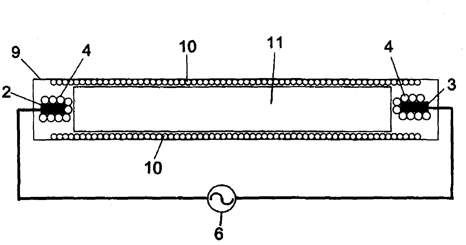
Provided is a fluorescent discharge lamp tube comprising a glass tube (9) filled therein with a discharge substance, a pair of metal electrodes (2 and 3) sealed at the two ends of the glass tube, and a fluorescent film (10) applied to the inner face of the glass tube. The metal electrodes are coated with insulator particles (4). The fluorescent film is formed of a mixture of particles of a fluorescent material for emitting a light when irradiated with an electron beam, and particles of a fluorescent material for emitting a light when irradiated with an ultraviolet ray. This fluorescent discharge lamp tube has a long lifetime because the metal electrodes are not exposed to a discharge space. Moreover, the fluorescent discharge lamp tube is lit within 10 milliseconds when fed with a high frequency.

Description

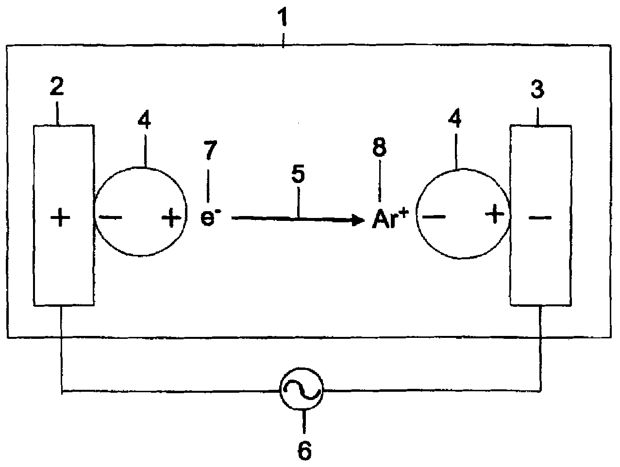
technical field [0001] The invention provides a fluorescent discharge lamp tube, which makes the mixed gas of argon (Ar) and mercury (Hg) vapor emit light through the inelastic collision of electrons, and passes through the fluorescent film coated on the inner wall surface of the fluorescent discharge lamp tube. And convert the strong 254nm invisible ultraviolet rays emitted by Hg into visible light. More specifically, the present invention provides a novel fluorescent discharge lamp and a liquid crystal display (LCD) display device using it. The basic structure of the discharge lamp can emit light with a high brightness that is more than twice the brightness of the conventional fluorescent lamp, although the power consumption required to turn on the discharge lamp is lower than that of the conventional fluorescent lamp. Background technique [0002] Outline of Conventional Discharge Lamp and the Invention [0003] The discharge of the existing fluorescent lamp tubes takes ...

Claims


Application Information

Patent Timeline
IPC IPC(8): H01J65/00H01J61/44F21S2/00F21Y103/00
CPCH01J65/046H01J61/305
Inventor 小泽隆二加藤正利原田将弘三吉稔美
Owner 北京千树万树互联网科技有限公司
Learn More