Cooling device

A heat dissipation device and heat dissipation fin technology, applied in indirect heat exchangers, heat exchange equipment, lighting and heating equipment, etc., can solve the problems of reducing the utilization rate of heat dissipation fins, small contact area, uneven temperature distribution, etc.

Inactive Publication Date: 2010-10-06
FU ZHUN PRECISION IND SHENZHEN +1
View PDF0 Cites 4 Cited by
  • Summary
  • Abstract
  • Description
  • Claims
  • Application Information

AI Technical Summary

Problems solved by technology

However, due to the high cost of the heat pipe, in order to control the cost, the number of heat pipes generally used in the cooling device is small, so that the contact area between the heat pipe and the heat dissipation fins is also small, which limits the heat transfer speed. The temperature in the area is high and the temperature in the area away from the heat pipe is low. The uneven temperature distribution greatly reduces the utilization rate of the cooling fins, thus limiting the heat dissipation performance of the cooling device.

Method used


Image

  • Cooling device
  • Cooling device
  • Cooling device

Examples


Embodiment Construction

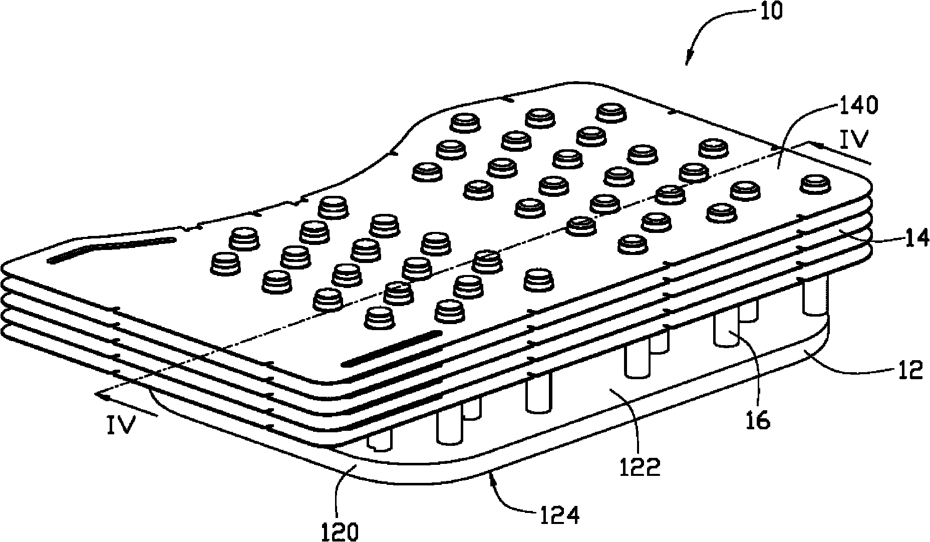
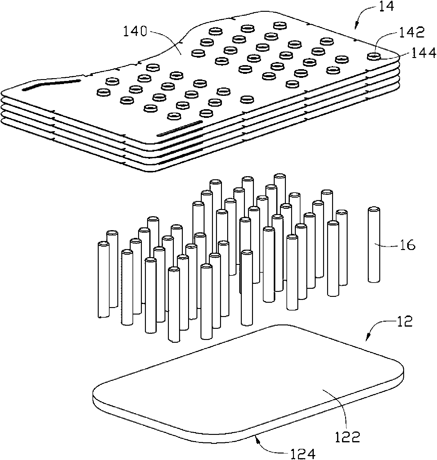
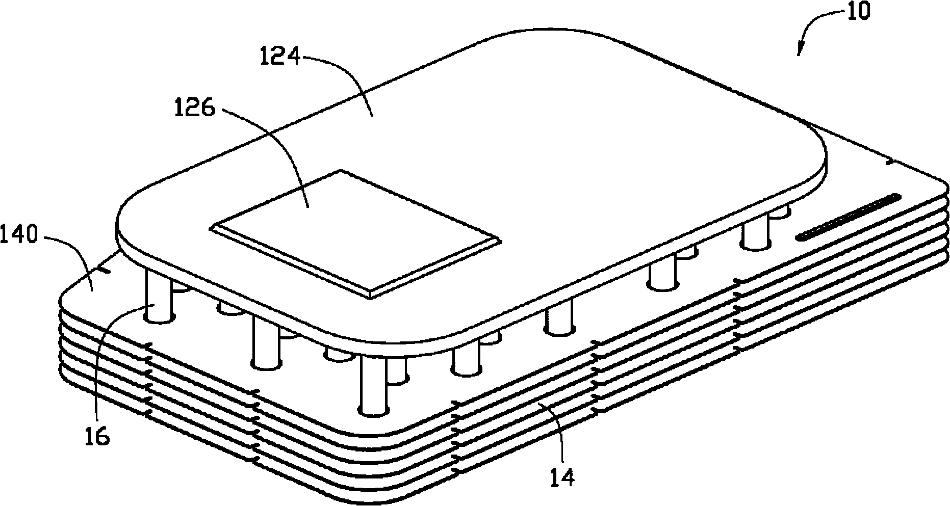
[0011] see Figure 1 to Figure 4 , the heat dissipation device 10 includes a plate-type heat pipe 12 , a heat dissipation fin set 14 and a plurality of heat transfer columns 16 .

[0012] The plate heat pipe 12 is flat and includes a shell 120 and a capillary structure 121 inside the shell 120 . The capillary structure 121 can be grooves, wire mesh, fibers or sintered powder. The casing 120 is made of a material with good thermal conductivity. The casing 120 encloses a hollow airtight chamber 125, and the chamber 125 contains a working medium (not shown in the figure) such as water, alcohol, and the like. The plate-type heat pipe 12 has a top surface 122 and a bottom surface 124 opposite thereto. The bottom surface 124 is used for contacting the heating electronic components to absorb heat generated by the heating electronic components. The bottom surface 124 protrudes outward to form a protruding portion 126 , and the protruding portion 126 is used for close contact with th...


PUM


Abstract

The invention relates to a cooling device. The cooling device comprises a plate type heat pipe, a plurality of cooling fins and a plurality of heat transfer columns, wherein the plate type heat pipe is used to contact with a heat source, a hollow sealed cavity is formed in the plate type heat pipe, working medium is filled in the hollow sealed cavity, one end of each heat transfer column is fixed on the plate type heat pipe, and the other end of the heat transfer column penetrates the cooling fins.

Description

technical field [0001] The invention relates to a heat dissipation device, in particular to a heat dissipation device suitable for heat dissipation of electronic components. Background technique [0002] With the rapid development of the information industry, heat-generating electronic components such as the central processing unit pursue high-speed, multi-functional and miniaturized heat dissipation problems are becoming more and more serious. Therefore, the heat must be dissipated in a timely and effective manner, otherwise it will be extremely serious The ground affects the performance of electronic components and also reduces the service life of electronic components, so it is necessary to dissipate heat from electronic components. [0003] Most of the current heat dissipation devices use a metal heat-absorbing base plate combined with a circular heat pipe and heat dissipation fins. The two ends of the heat pipe are respectively connected to the heat-absorbing base plate...

Claims


Application Information

Patent Timeline
Patent Type & Authority Applications(China)
IPC IPC(8): F28D15/02F28F1/30F28F21/08H05K7/20G06F1/20H01L23/36
CPCF28D15/0233F28F3/022F28F1/32H01L23/427F28F3/02F28D15/04H01L2924/0002H01L2924/00
Inventor 刘鹏周世文陈俊吉
Owner FU ZHUN PRECISION IND SHENZHEN
Why Eureka
Try Eureka