
Textile printing and dyeing wastewater treatment device and technology

A technology for wastewater treatment, textile printing and dyeing, applied in the fields of environmental protection and water treatment, can solve the problems of oxygen consumption, affecting the effect of wastewater treatment, complex design structure, etc. Effect

Inactive Publication Date: 2010-08-11
GUANGDONG ESQUEL TEXTILES
View PDF7 Cites 3 Cited by
  • Summary
  • Abstract
  • Description
  • Claims
  • Application Information

AI Technical Summary

Problems solved by technology

[0007] The ozonation and biological aerated filter in the above-mentioned prior art has a complex design structure, and is mostly used in the advanced treatment process of wastewater physical and chemical treatment or biochemical treatment of effluent. Before the ozonation and biological aerated filter is treated, more Physicochemical or biochemical sludge. In addition, the textile printing and dyeing stage uses sodium sulfate (sodium sulfate) as a dyeing accelerator, resulting in a large amount of sulfate ions in the printing and dyeing wastewater. During the anaerobic hydrolysis acidification treatment stage, the sulfate is reduced to sulfur Part of the sulfide is converted into hydrogen sulfide gas and escapes into the air above the polluted water plant and the surrounding area. The residual sulfide in the water enters the aerobic biological treatment stage, which consumes a large amount of oxygen and affects the wastewater treatment effect.

Method used


Image

  • Textile printing and dyeing wastewater treatment device and technology
  • Textile printing and dyeing wastewater treatment device and technology
  • Textile printing and dyeing wastewater treatment device and technology

Examples


Embodiment

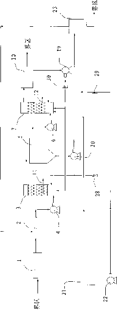
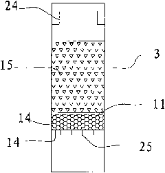
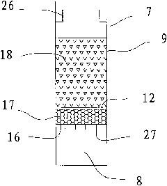
[0022] refer to figure 1 , 2And 3, a textile printing and dyeing wastewater treatment device, comprising a grid 1 connected in sequence, a regulating buffer tank 2, a first water inlet pump 4, a biological peristaltic bed 3, a sedimentation buffer tank 5, a second water inlet pump 6, an ozone-exposure Gas biofilter 7, clean water pool 10, wherein the inlet pipeline of the first water inlet pump 4 is connected to the adjustment buffer tank 2, and the outlet pipeline is connected to the water inlet at the bottom of the biological peristaltic bed 3, and the biological peristaltic bed 3 is provided with a filter plate 13, on which A cobblestone cushion 14 and a biological ceramsite layer 15 are provided from bottom to top, a first aeration pipe 11 is provided at 100-200 mm above the filter plate 13, a long handle filter head 25 is provided on the filter plate 13, and the biological peristaltic bed 3 The top is provided with a pipeline connected to the outlet weir 24 of the sedime...


PUM


Abstract

The invention discloses a textile printing and dyeing wastewater treatment device and technology. The technology comprises the following steps: a first intake pump is used to pump wastewater into the bottom of a biological creeping bed, wastewater passes through a first biological haydite layer from bottom to top, the top effluent enters in a sedimentation and filtration ditch to precipitate, a second intake pump is used to pump the upper clear water into the ozone reaction area on the bottom of an ozone-aeration biological filter while 50-75mg / L of ozone is injected, then the reacted water passes through a second biological haydite layer from bottom to top, the clean water overflowing from the top enters a clear water reservoir, the clear water in the clear water reservoir is sent to the outside for emission or for advanced treatment and reuse. The invention has the advantages that the adhesion of microorganism in the system is good, the aeration rate is enough and enough biological concentration can be maintained, thus the volume load is increased, the sludge load is reduced, the amount of sludge can be obviously reduced; and as ozone is used to remove organics which are difficult to degrade, the entire technology is under the aerobic environment, sulfides generated in the anaerobe treatment process can be avoided and physical and chemical sludge generated in the coagulating sedimentation process can be eliminated.

Description

technical field [0001] The invention belongs to the technical fields of environmental protection and water treatment, and in particular relates to a device and a process for treating textile printing and dyeing wastewater. Background technique [0002] Textile printing and dyeing wastewater has the characteristics of large water volume, high content of organic pollutants, many refractory substances, high chroma, and complex components. It is a difficult-to-treat industrial wastewater. Printing and dyeing wastewater contains dyes, sizing agents, additives, oil agents, acids and bases, fiber impurities and inorganic salts, etc., which have high biological toxicity and seriously pollute the environment. At present, the unit operations of printing and dyeing wastewater treatment at home and abroad can be divided according to the principles: physical treatment methods (dilution method, natural sedimentation method, filtration method, adsorption method, centrifugal separation meth...

Claims


Application Information

Patent Timeline
IPC IPC(8): C02F9/14C02F1/78C02F3/06C02F103/30
CPCY02W10/10
Inventor 张玉高邱孝群付志敏
Owner GUANGDONG ESQUEL TEXTILES
Learn More