Multiplex pulse laser integrated system

An integrated system, multi-channel pulse technology, applied in optics, optical components, instruments, etc., can solve problems such as loss of beam energy, and achieve the effect of sufficient pulse energy, high energy stability, and no loss of light energy

Inactive Publication Date: 2010-08-04
WENZHOU MEDICAL UNIV +1
View PDF0 Cites 8 Cited by
  • Summary
  • Abstract
  • Description
  • Claims
  • Application Information

AI Technical Summary

Problems solved by technology

[0003] The purpose of the present invention is to overcome the defect that the existing dual optical path synthesis system loses beam energy during the synthesis process, and to provide a system that can avoid the loss of laser energy due to the use of an optical beam splitter, and at the same time meet the requirements of high pulse frequency and high energy stability. A multi-channel pulse laser integrated system that meets the requirements of high reliability and sufficient pulse energy

Method used


Image

  • Multiplex pulse laser integrated system
  • Multiplex pulse laser integrated system
  • Multiplex pulse laser integrated system

Examples


specific Embodiment 1

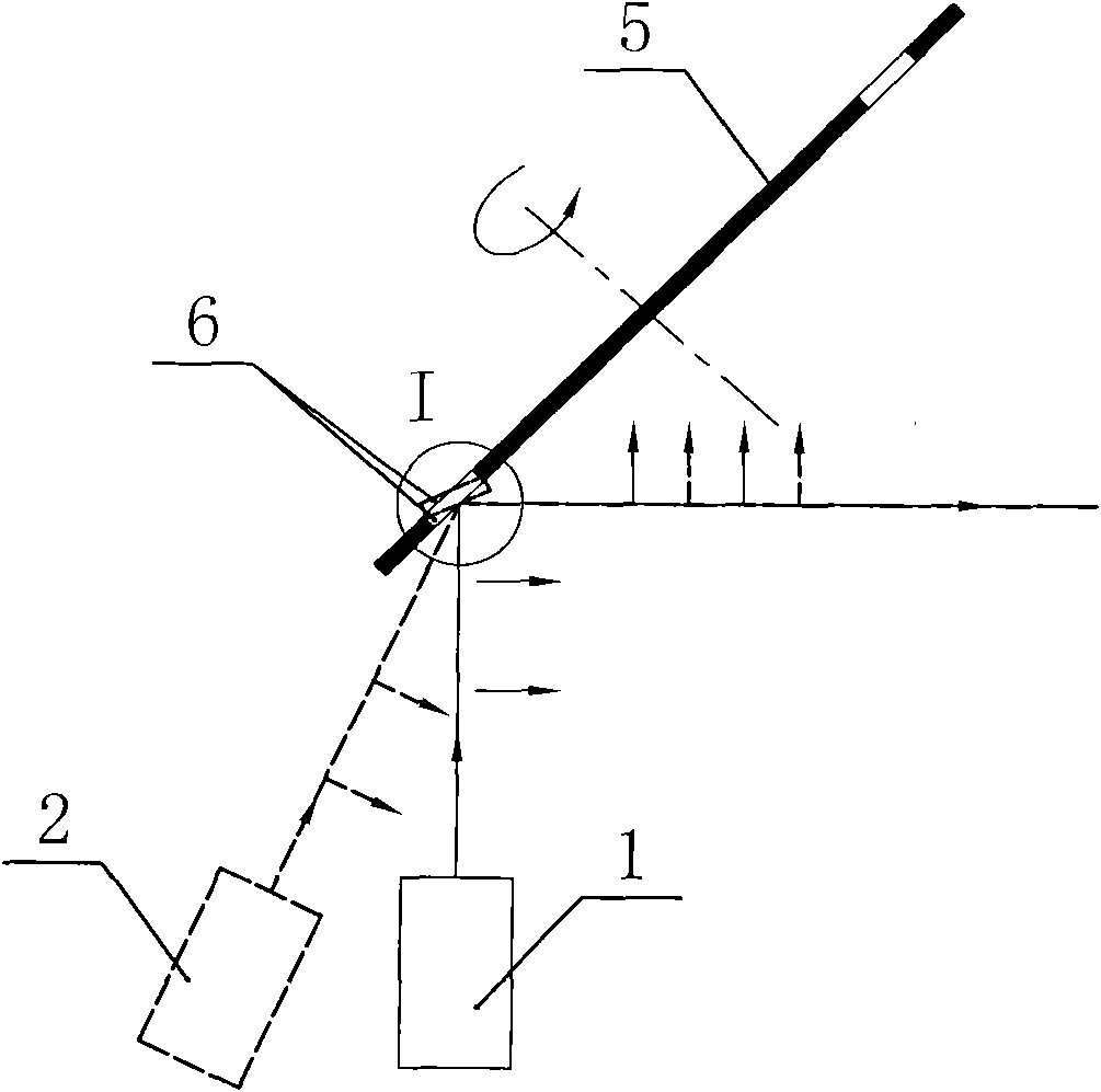
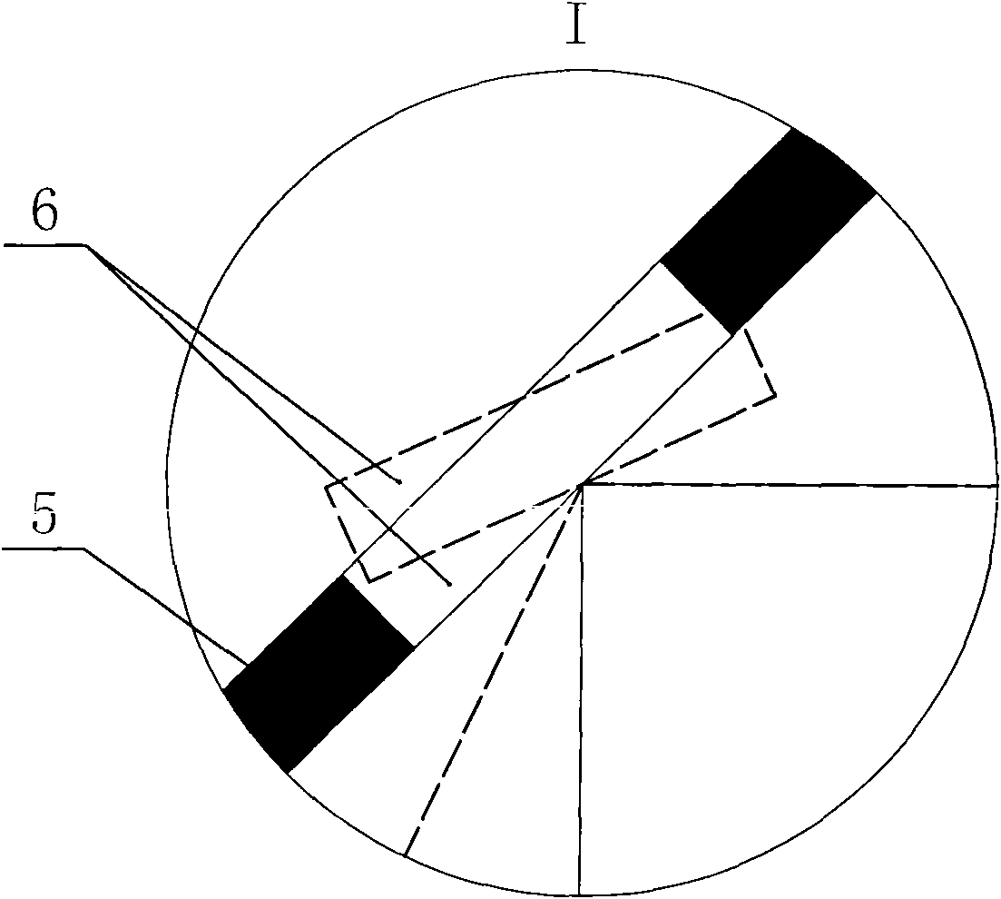
[0014] Specific embodiment 1: the synthesizing mechanism of multi-channel pulsed laser integration system adopts reflector group, the number of reflector 3 in the reflector group is the same as the number of laser sources, and the light beams that each laser source sends aim at the same point that is intersection point 4, The angles of each reflector 3 correspond to the laser source one by one, so that when the reflector driving device drives the reflector 3 to pass through the intersection point 4 of the laser source one by one, the light emitted by the laser source is in the same state after being reflected by the corresponding reflector 3. On one optical path, the mirror driving device (not shown in the figure) drives the mirror group to circulate through the intersection point 4 one by one under the control of the synchronizer (not shown in the figure), and the mirror group is at least one group, or Multiple groups pass through the junction 4 repeatedly, and the synchronize...

specific Embodiment 2

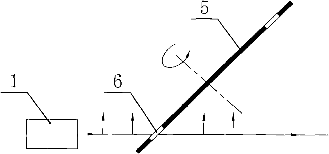
[0015] Specific embodiment 2: this specific embodiment can also take the following mode: each group of reflecting mirror groups includes a light transmission hole 6, each group of light transmission holes 6 plus the number of reflection mirrors 3 is the same as the number of laser sources, and the mounting frame 5 is composed of The mirror driving device is driven to rotate around the central axis. The first laser source 1 in the plurality of laser sources is arranged on the rear side of the mounting frame 5, and the remaining laser sources are arranged on the other side of the mounting frame 5. All laser sources emit The intersection point 4 of the light beam falls on the trajectory of the mirror group rotation, and the light beams sent by the other laser sources except the first laser source 1 overlap with the light beams sent by the first laser source 1 after being reflected by the corresponding reflector 3, so that This avoids the problem that all reflectors 3 need to be ca...


PUM


Abstract

The invention relates to a multiplex pulse laser integrated system, in particular to a multiplex pulse laser integrated system used in an excimer laser refractive surgical instrument. The method separately uses laser sources to send out light in different times, the light paths of all the laser sources have one intersection; a synthesizing mechanism contains at least one group of reflectors in different angles, a reflector driving device and a synchronizer, wherein the reflector driving device drives the group of reflectors to circularly pass through the intersection one by one, and the angle of each reflector in the group of reflectors corresponds to the laser sources so that when the reflector driving device drives the group of reflectors to pass through the intersection one by one, light sent by the laser sources passes through the corresponding reflector and is reflected to be in one light path. Therefore, the laser light source of the excimer laser refractive surgical instrument can satisfy the demands of high pulse frequency, high energy stability and enough pulse energy and the technical solution is provided for the clinical application of the excimer laser refractive surgical instrument.

Description

technical field [0001] The invention relates to a multi-channel pulsed laser integrated system, especially a multi-channel pulsed laser integrated system used on an excimer laser ophthalmology treatment machine, which realizes the optical path multiplexing of two or more laser beams to obtain high pulse frequency, Laser with high energy stability and sufficient pulse energy. Background technique [0002] As the core part of excimer laser therapy equipment, laser light source has high technical requirements, and the quality of laser light source will directly affect the effect of surgery. In order to meet the requirements of excimer laser ophthalmology treatment, the laser light source used must meet the three requirements of high pulse frequency, high energy stability and sufficient pulse energy. For an excimer laser, the higher the pulse energy, the more expensive it is; and when the laser works at a high speed such as 500Hz, the system needs to add a water cooling system,...

Claims


Application Information

Patent Timeline
Patent Type & Authority Applications(China)
IPC IPC(8): G02B27/14G02B26/08
Inventor 瞿佳刘党会吕帆陈浩厉以宇
Owner WENZHOU MEDICAL UNIV
Why Eureka
Try Eureka