On-line detection device and detection method for open-circuit fault of power tubes of inverter
A technology for open-circuit faults and detection devices, which can be used in measurement devices, instruments, measurement electronics, etc., and can solve problems such as increased hardware cost and complexity, and slow detection speed.
- Summary
- Abstract
- Description
- Claims
- Application Information
AI Technical Summary
Problems solved by technology
Method used
Image
Examples
specific Embodiment approach 1
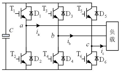
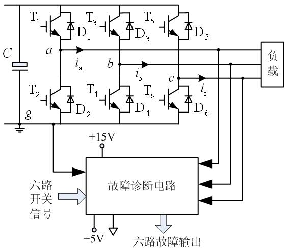
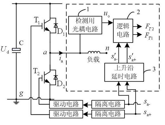
[0012] Specific implementation mode one: combine Figure 2 to Figure 4 To illustrate this embodiment, the online detection device for inverter power tube open circuit fault in this embodiment is provided with three inverter circuit input terminals, six switch signal input terminals and six fault output terminals;
[0013] The online detection device for the open circuit fault of the power tube of the inverter is composed of three online detection circuits for the open circuit fault of the power tube; a On-line detection circuit for the open circuit fault of the power tube of the phase bridge arm, b On-line detection circuit of phase arm power tube open circuit fault and c On-line detection circuit for open-circuit fault of power tube of phase bridge arm;
[0014] The online detection circuit of each power tube open circuit fault is composed of an optocoupler circuit 1 for detection, a logic circuit 2 and a rising edge delay circuit 3; each power tube open circuit fault onlin...
specific Embodiment approach 2
[0019] Specific implementation mode two: combination Figure 4 Describe this embodiment, the difference between this embodiment and specific embodiment 1 is that the optocoupler circuit 1 for detection is composed of a high-speed optocoupler P, a fast recovery diode D g , capacitor C and two resistors; fast recovery diode D g The cathode is the input terminal of the detection optocoupler circuit 1, which is used to collect the output signal of a bridge arm circuit in the detected inverter; the fast recovery diode D g The anode of the high-speed optocoupler P is connected to the cathode of the light-emitting diode, the anode of the light-emitting diode in the high-speed optocoupler P is connected to one end of the first resistor R1, and the other end of the first resistor R1 is connected to the +15V power supply. The emitter of the phototransistor in the coupler P is connected to the +5V power supply ground and one end of the capacitor C at the same time, and the collector of ...
specific Embodiment approach 3
[0020] Specific implementation mode three: combination Figure 4 Describe this embodiment, the difference between this embodiment and specific embodiment one is that the logic circuit 2 is made up of an inverter and two NAND gates; the signal received by the signal input end of the logic circuit 2 is sent to the first NAND One input terminal of the gate and the input terminal of the inverter, the switching signal received by one switching signal input terminal of the logic circuit 2 is sent to the other input terminal of the first NAND gate, and the other switching signal input terminal of the logic circuit 2 The received switch signal is sent to one input terminal of the second NAND gate, the other input terminal of the second NAND gate receives the inversion signal sent by the output terminal of the inverter, and the output terminal of the first NAND gate and The output terminal of the second NAND gate outputs the lower power tube fault signal and the upper power tube fault ...
PUM
 Abstract
Description
Claims
Application Information
 - R&D
- Intellectual Property
- Life Sciences
- Materials
- Tech Scout
- Unparalleled Data Quality
- Higher Quality Content
- 60% Fewer Hallucinations
Browse by: Latest US Patents, China's latest patents, Technical Efficacy Thesaurus, Application Domain, Technology Topic, Popular Technical Reports.
© 2025 PatSnap. All rights reserved.Legal|Privacy policy|Modern Slavery Act Transparency Statement|Sitemap|About US| Contact US: help@patsnap.com


