
Simulation test method of thermal fatigue failure of blade with thermal barrier coating

A technology for simulating testing and thermal fatigue, which is applied to thermometers, measuring devices, and heat measurement of directly heat-sensitive electric/magnetic components, which can solve difficult fatigue failures, failure to test blade deformation, and failure to achieve deformation, etc. question

Active Publication Date: 2012-05-02
湖南新生代新材料科技有限公司
View PDF1 Cites 5 Cited by
  • Summary
  • Abstract
  • Description
  • Claims
  • Application Information

AI Technical Summary

Problems solved by technology

This patent mainly defines the longitudinal allowable strain of the turbine blade, and cannot test the deformation of the entire blade, so it is difficult to predict its fatigue failure based on the overall deformation of the blade; at the same time, it is not possible to test the blade in all directions in real time in a high temperature environment. deformation, has not been involved in thermal fatigue failure of blades with thermal barrier coatings

Method used


Image

  • Simulation test method of thermal fatigue failure of blade with thermal barrier coating
  • Simulation test method of thermal fatigue failure of blade with thermal barrier coating
  • Simulation test method of thermal fatigue failure of blade with thermal barrier coating

Examples


Embodiment Construction

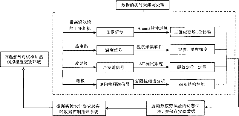
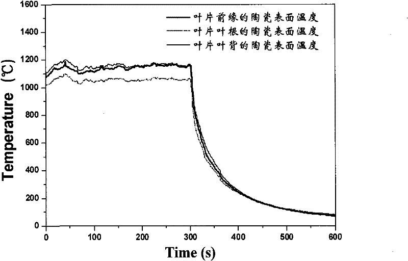
[0045] The present invention relates to a simulation test method for thermal fatigue failure of a blade with a thermal barrier coating in an aero turbine engine. The implementation of this patent will be further described in detail below in conjunction with the accompanying drawings.

[0046] figure 1 It is a flowchart of the real-time testing method for thermal fatigue failure of a turbine blade provided by the present invention. This embodiment can be carried out according to the following steps:

[0047] The first step is to prepare the sample: the plasma spraying process is used to spray the thermal barrier coating heat insulation material on the surface of a certain type of hollow turbine blade. Its system composition is: transition layer material is NiCrAIY alloy, its thickness is about 100μm; ceramic powder material is containing 8% Y 2 o 3 ZrO 2 , the thickness of the ceramic layer is about 300 μm. Then spray a layer of anti-color ultra-high temperature resistant ...


PUM

PropertyMeasurementUnit
thicknessaaaaaaaaaa
thicknessaaaaaaaaaa

Abstract

The invention belongs to the technical field of turbine blade performance detection in the aviation industry, in particular to a simulation test method of thermal fatigue failure of a blade with thermal barrier coating. The method can simulate the thermal fatigue work environment of temperature alternating circulation of various blades in an aircraft engine with high performance, and simultaneously tests and analyzes data, such as temperature, temperature gradient, surface topography image evolution, three dimensional deformation field, three dimensional displacement field, interface oxidation layer and thickening rule thereof, thermal fatigue flaw initiation and expansion, cooling airflow and the like of a blade sample with a thermal barrier coating, thus realizing real-time monitoring of three dimensional thermal strain and stress of the blade in the process of thermal fatigue experiments, and providing an important means for predicting thermal fatigue damaging position and invalidation time of the blade. The experimental data obtained by the method can provide important experiment basis for effectively evaluating the failure mechanism of the aircraft engine blade in the environment of high-temperature gas and predicting ceramic coating dropping position, dropping time and service life.

Description

technical field [0001] The invention belongs to the technical field of turbine blade performance detection in the aviation industry, in particular to a method for testing the thermal fatigue performance and failure process of high-temperature components under thermal cycle conditions, and in particular to a thermal barrier coating used in an aircraft turbine engine A simulation test method for thermal fatigue failure of blades with layers. Background technique [0002] In recent years, with the development of aero-engines towards high bypass ratio, high thrust-to-weight ratio, and high turbine inlet temperature, the operating temperature of the engine is getting higher and higher, and the turbine inlet temperature has become a key indicator to measure the performance of the engine. The turbine inlet temperature of modern aero turbine engines can reach up to 1800K or even 2000K (about 1727 degrees Celsius, which exceeds the melting point of most metal materials). In order to...

Claims


Application Information

Patent Timeline
Patent Type & Authority Patents(China)
IPC IPC(8): G01N29/14G01N27/04G01B11/16G01B11/02G01B11/24G01K7/02
Inventor 毛卫国周益春吴多锦杨丽
Owner 湖南新生代新材料科技有限公司
Learn More