
RF (radio frequency) receiving front end with diversified gaining modes and capable of automatic tuning

A technology of radio frequency reception and automatic tuning, which is applied in the direction of multi-frequency modulation conversion, amplification control, and control of components of the amplification device, etc., which can solve the problem that the switch cannot be effectively turned off, the performance of the filter is affected, and the total capacitance value of the capacitor array is not stable. Accuracy and other issues

Active Publication Date: 2010-06-23
TSINGHUA UNIV
View PDF2 Cites 27 Cited by
  • Summary
  • Abstract
  • Description
  • Claims
  • Application Information

AI Technical Summary

Problems solved by technology

In view of the problem that the resistance and capacitance in the active RC filter will vary with the process and temperature, some correction methods have been proposed. For example, some literature discloses a circuit for correcting the RC time constant, but does not give a correction The specific correction method of the RC filter and the connection method of the circuit did not give a reasonable and fast correction algorithm
And no one has given an effective implementation method of the capacitor array at present. The traditional method is to use NMOS transistors, PMOS transistors or CMOS transmission gates as switches, which are directly connected in series with the capacitors. However, when the switch is turned off, the connection point between the switch and the capacitor The DC level is uncertain, which will cause the switch to not be effectively turned off in many cases, resulting in inaccurate total capacitance value of the capacitor array, which seriously affects the performance of the filter

Method used


Image

  • RF (radio frequency) receiving front end with diversified gaining modes and capable of automatic tuning
  • RF (radio frequency) receiving front end with diversified gaining modes and capable of automatic tuning
  • RF (radio frequency) receiving front end with diversified gaining modes and capable of automatic tuning

Examples


Embodiment Construction

[0051] The specific implementation manners of the present invention will be further described in detail below in conjunction with the accompanying drawings and embodiments. The following examples are used to illustrate the present invention, but are not intended to limit the scope of the present invention.

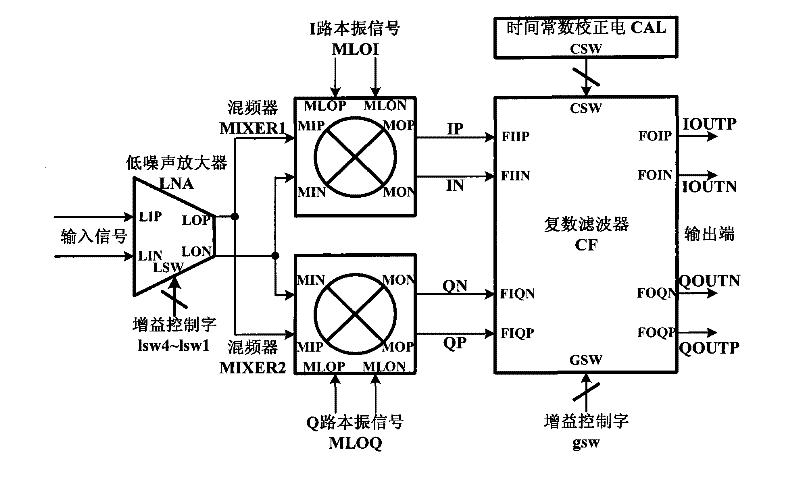
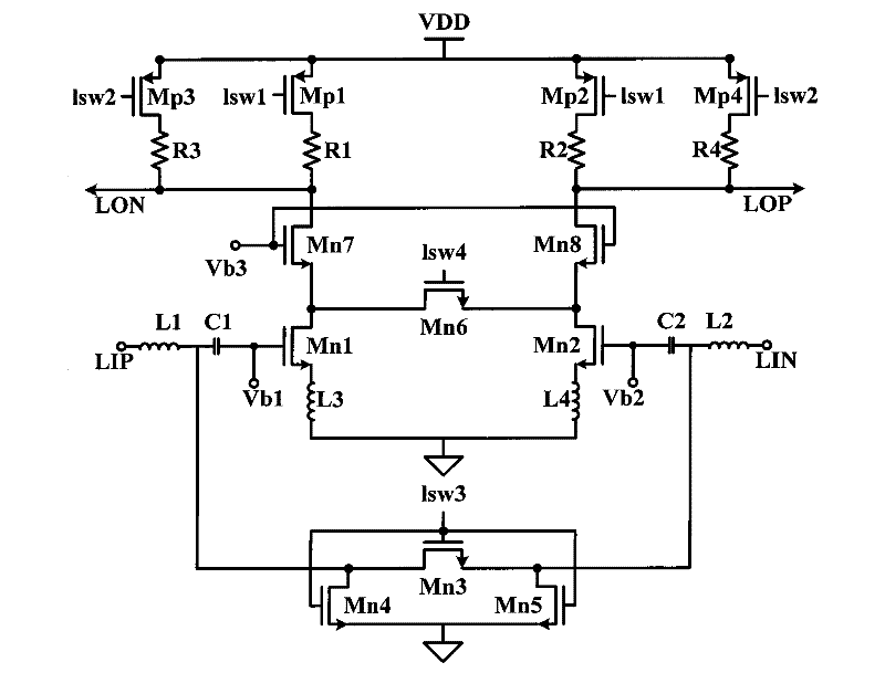
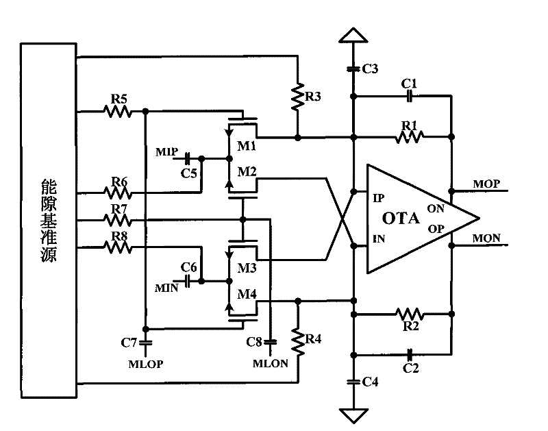
[0052] The block diagram of the radio frequency receiving front-end circuit that has multiple gain modes and can be automatically tuned according to the embodiment of the present invention is as follows figure 1 As shown, the differential input terminals LIP and LIN of the low noise amplifier LNA are connected to the input signal, and the gain control terminal LSW of the low noise amplifier is connected to the gain control words lsw4˜lsw1. The differential input terminals MIP and MIN of the I-channel mixer MIXER1 and the Q-channel mixer MIXER2 are respectively connected to the differential output terminals LOP and LON of the LNA, and the local oscillator signal differentia...


PUM


Abstract

The invention discloses an RF (radio frequency) receiving front end with diversified gaining modes and capable of automatic tuning. The RF receiving front end comprises a low-noise amplifier, a frequency mixer, a complex filter and a time constant correcting circuit. The input end of the low-noise amplifier is connected with an input signal, and the output end adopts NC (numerical control) resistance as load to correct gains; the differential input ends of the I-path frequency mixer and the Q-path frequency mixer are respectively connected to the output end of the low-noise amplifier, and thedifferential output ends are respectively connected to the differential input end of the complex filter; the complex filter which adopts a multi-stage cascaded structure realizes the diversified gaining modes by the NC resistance, and meanwhile a time constant can realize tuning by controlling a capacitance array; and the output end of the time constant correcting circuit is connected with the correcting control word input end of the complex filter. By combining the current-mode low-noise amplifier, the passive frequency mixer and the active RC complex filter with each other, the RF receivingfront end has the advantages of low noise, high linearity, low power consumption, low cost and the like.

Description

technical field [0001] The invention relates to the technical field of radio frequency receiving front end, in particular to a radio frequency receiving front end with multiple gain modes and capable of automatic tuning. Background technique [0002] In radio frequency receivers, many applications often require the received signal to have a large dynamic range, that is, to have small receiving sensitivity, strong anti-large signal saturation capability and high linearity. The noise figure of the receiving front end of the radio frequency receiver directly determines the receiving sensitivity of the receiver, and the gain and structure of the receiving front end determine the receiver's ability to resist large signal saturation and linearity. In the CMOS (Complementary Metal Oxide Semiconductor) process, the resistance and capacitance will deviate with the process and temperature, which will seriously affect the performance of the receiver, especially the receiver using an ac...

Claims


Application Information

Patent Timeline
IPC IPC(8): H04B1/16H03F3/45H03G1/00H03D7/16H03H1/02
Inventor 赵博杨华中
Owner TSINGHUA UNIV
Learn More