
Method for preparing pliers of butted cutting edges

A production method and cutting edge technology, which is applied in the field of mechanical design, can solve the problems that it is difficult to completely avoid the dislocation of the cutting edge, it is difficult to ensure that the two cutting edges coincide, and it is not suitable for high-hardness cutting edges. Good sharpness and durability

Inactive Publication Date: 2012-09-05
洪殿
View PDF0 Cites 0 Cited by
  • Summary
  • Abstract
  • Description
  • Claims
  • Application Information

AI Technical Summary

Problems solved by technology

[0004] (2) The cutting edge made by powder metallurgy (PM) has uneven internal structure, the overall density is lower than that of precision casting, and the hardness after heat treatment is about HRC40, which is not suitable for making high hardness cutting edge
[0005] (3) After the two cutting edges are manufactured separately, they are assembled and then trimmed. It is difficult to ensure a sufficient fit between the two cutting edges, and the misalignment between the cutting edges is difficult to avoid completely, and the effect is poor when used.

Method used


Image

  • Method for preparing pliers of butted cutting edges
  • Method for preparing pliers of butted cutting edges
  • Method for preparing pliers of butted cutting edges

Examples


Embodiment 1

[0022] Follow these steps to make butt edge pliers:

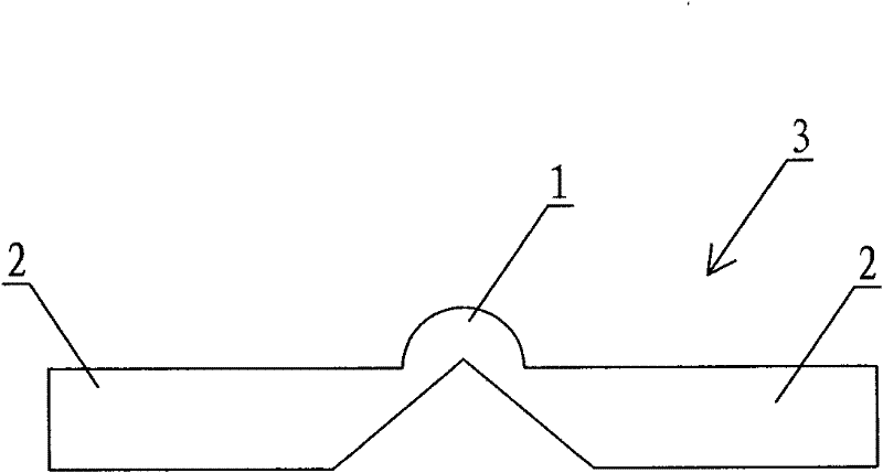
[0023] (1), making a mold with integrally formed butt joint cutting edges, wherein the mold includes left and right relative cutting edge cavities, the wedge-shaped ends of the cutting edge cavities are opposite to each other, and connecting portion cavities are also provided between the cutting edge cavities;

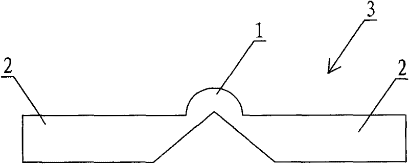
[0024] (2), put the mold obtained in step (1) into a metal powder injection molding machine, and produce an integrated butt joint cutting edge 3 including the connecting part 1 through metal powder injection molding, degreasing, sintering, and heat treatment, wherein the integrated Butt cutting edge 3 comprises a pair of cutting edge 2 and connection part 1 opposite left and right, and connection part 1 connects the end face of the wedge-shaped end of cutting edge 2 together (as figure 1 shown);

[0025] (3), riveting the integrated butt joint cutting edge 3 obtained in step (2) on the pliers body to obtain the pli...

Embodiment 2

[0029] Follow these steps to make butt edge pliers:

[0030] (1), making a mold with integrally formed butt joint cutting edges, wherein the mold includes left and right relative cutting edge cavities, the wedge-shaped ends of the cutting edge cavities are opposite to each other, and connecting portion cavities are also provided between the cutting edge cavities;

[0031] (2), put the mold obtained in step (1) into a metal powder injection molding machine, and produce an integrated butt joint cutting edge 3 including the connecting part 1 through metal powder injection molding, degreasing, sintering, and heat treatment, wherein the integrated Butt cutting edge 3 comprises a pair of cutting edge 2 and connection part 1 opposite left and right, and connection part 1 connects the end face of the wedge-shaped end of cutting edge 2 together (as figure 1 shown);

[0032] (3), the integrated butt joint cutting edge 3 that step (2) is made is welded on the pliers body, makes the plie...

Embodiment 3

[0035] Follow these steps to make butt edge pliers:

[0036] (1), making a mold with integrally formed butt joint cutting edges, wherein the mold includes left and right relative cutting edge cavities, the wedge-shaped ends of the cutting edge cavities are opposite to each other, and connecting portion cavities are also provided between the cutting edge cavities;

[0037] (2), put the mold obtained in step (1) into a metal powder injection molding machine, and produce an integrated butt joint cutting edge 3 including the connecting part 1 through metal powder injection molding, degreasing, sintering, and heat treatment, wherein the integrated Butt cutting edge 3 comprises a pair of cutting edge 2 and connection part 1 opposite left and right, and connection part 1 connects the end face of the wedge-shaped end of cutting edge 2 together (as figure 1 shown);

[0038] (3), the integrated butt joint cutting edge 3 obtained in step (2) is installed on the caliper body by riveting ...


PUM


Abstract

The invention discloses a method for preparing pliers of butted cutting edges, comprising the following steps: (1) preparing an all-in-one mould of the butted cutting edges, wherein the mould comprises the left mould cavity of cutting edge and the right cavity of cutting edge which are opposite to each other, and the wedge-shaped ends of the mould cavities of cutting edges are opposite to each other, and a connecting part of mould cavity is installed between the mould cavities of cutting edges; (2) loading the mould obtained in step (1) into the metal powder injection molding machine, and preparing an integration of butted cutting edges and connecting part by injecting and forming in metal powder, degreasing, sintering and heat treating, wherein the integration of butted cutting edges comprises a left cutting edge and a right cutting edge which are opposite to each other, and the connecting part is used for connecting the two end faces of the wedge-shaped ends of the cutting edges; (3) mounting the integration of butted cutting edges obtained in step (2) on the pliers so as to prepare the blank of pliers; (4) removing the connecting part of the integration of butted cutting edges in the blank of pliers which is obtained in step (3) by grinding wheel so as to prepare the pliers of butted cutting edges. The pliers of butted cutting edges prepared by the invention have good property, sharpness and durability and high finished product ratio, and the pliers are not easy to misplace.

Description

technical field [0001] The invention relates to the field of mechanical design, in particular to a method for manufacturing butt-joint cutting edge pliers. Background technique [0002] At present, most of the pliers cutting tools such as nail clippers, beauty pliers, and electrician pliers use arc-shaped straight-line or inclined-plane straight-line cutting edges. In traditional industries, such cutting edges are basically formed by stamping, forging Forming, casting molding, precision casting molding and other methods, there are certain defects: [0003] (1) The cutting edge made by stamping forming, precision casting and other processes is only suitable for low-carbon and low-alloy materials. The performance of the product (including hardness, toughness and other indicators) is not good, and the sharpness and durability of the cutting edge are not good. It is very ideal; while the edge performance produced by forging is better, but the size of the workpiece is difficult ...

Claims


Application Information

Patent Timeline
Patent Type & Authority Patents(China)
IPC IPC(8): B23P15/28B22F3/12B22F3/24
Inventor 洪殿
Owner 洪殿
Learn More