
Large-power dye-sensitized solar cell

A technology for solar cells and dye sensitization, applied in the field of solar cells, can solve the problems of increasing the internal resistance of the battery, reducing the battery performance, and volatile organic solvents, and achieving the effects of improving performance, improving reliability and reducing transmission distance.

Inactive Publication Date: 2010-04-14
EAST CHINA NORMAL UNIV
View PDF0 Cites 12 Cited by
  • Summary
  • Abstract
  • Description
  • Claims
  • Application Information

AI Technical Summary

Problems solved by technology

At present, DSC mainly adopts the - / I 3 - Although the liquid electrolyte of the redox couple has high photoelectric conversion efficiency, it is difficult to seal the battery because the liquid electrolyte is easy to leak and the organic solvent is easy to volatilize. The liquid electrolyte contains I - / I 3 - The redox pair is a chemically active and highly corrosive substance. During the long-term operation of the battery, the electrolyte corrodes the deposited grid conductive electrode, resulting in a decrease in battery performance and a shortened service life.
The reliability and stability of DSC devices have great limitations
In addition, the distance between the two stages of the battery has a great influence on the performance of the battery: if the distance is too large, it is easy to increase the internal resistance of the battery and reduce the performance of the battery; if the distance is too small, it is easy to cause a short circuit inside the battery
The unevenness of the internal spacing of the battery can also easily affect the repeatability and stability of the DSC device

Method used


Image

  • Large-power dye-sensitized solar cell
  • Large-power dye-sensitized solar cell
  • Large-power dye-sensitized solar cell

Examples


Embodiment 1

[0037] Glass Substrate Solar Cells

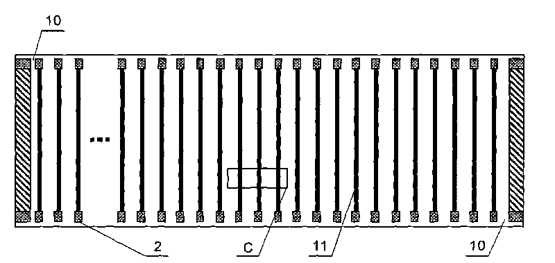
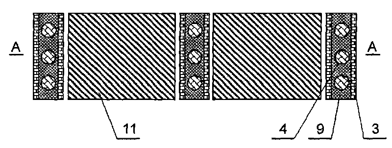
[0038] Preparation of TiO according to the process of making dye-sensitized monolithic solar cells 2 Colloidal solution and made into slurry, and prepare platinum counter electrode, silver glue and other screen printing paste, evenly mix the isolation material balls into low melting point glass powder to prepare the sealing paste, prepare to prepare TiO 2 Nanoporous film, platinum counter electrode, silver glue wire, glass powder wire. The positions of the thin film layers and electrodes are as follows: image 3 shown. Preparation process and steps: (1) The upper and lower substrates are made of transparent conductive TCO glass and cleaned, followed by ultrasonic cleaning with acetone, alcohol, and deionized water for 15 minutes, and then dried with pure nitrogen; (2) Silk screen Printing of various functional layers: including nano-TiO 2Thin film, platinum counter electrode layer, silver glue electrode, mixed glass powder line for isol...

Embodiment 2

[0040] Stainless Steel Substrate Solar Cell

[0041] Preparation of TiO according to the process of making dye-sensitized monolithic solar cells 2 Colloidal solution and paste, and prepare screen printing paste such as silver glue, ready to prepare TiO 2 nanoporous films. The positions of the thin film layers and electrodes are as follows: Figure 5 shown. Preparation process and steps: (1) The upper substrate is made of a transparent polymer plate (ITO-PET, ITO-PEN), the lower substrate is made of a stainless steel plate, and they are cleaned, followed by ultrasonic cleaning with acetone, alcohol, and deionized water for 15 minutes. (2) Sputter a layer of Pt counter electrode and Ag electrode on the transparent polymer substrate; (3) Spray glass spheres on the stainless steel substrate, and the glass spheres are evenly and sparsely distributed on the whole surface. (4) screen printing each functional layer, including nano-TiO 2 Thin film and silver glue electrodes are on...

Embodiment 3

[0043] Polymer Substrate Solar Cells

[0044] Preparation of TiO according to the process of making dye-sensitized monolithic solar cells 2 Colloidal solution and made into slurry, ready to prepare TiO 2 Nanoporous film; the positions of each film layer and electrodes are as follows Figure 5 shown. Preparation process and steps: (1) The upper and lower substrates are made of transparent polymer plates (ITO-PET, ITO-PEN) and cleaned, followed by ultrasonic cleaning with acetone, alcohol, and deionized water for 15 minutes, and then with pure (2) Sputter a layer of Pt counter electrode and Ag electrode on the transparent polymer substrate; (3) Spray glass balls on another transparent polymer substrate, and the glass balls are evenly and sparsely distributed on the whole (4) Deposit a layer of TiO on the substrate by embossing, screen printing, etc. 2 Thin film, sputtering Ag electrode; (5) drying or hydrothermal treatment, the sample is placed in a convection oven or a hydr...


PUM

PropertyMeasurementUnit
diameteraaaaaaaaaa

Abstract

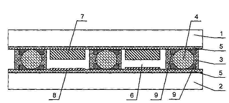
The invention discloses a large-power dye-sensitized solar cell. The solar cell comprises a plurality of strip-shaped monomer dye-sensitized solar cells (DSC) that are connected in series or in parallel. The solar cell comprises an upper substrate and a lower substrate, and both of the two substrates face to each other and comprise a plurality of strip-shaped monomer cell areas; a light-anode and a counter electrode are formed on the upper substrate and the lower substrate respectively; and the dye is adsorbed on the photo-anode. The upper substrate and the lower substrate are sealed by glass dust of low melting point or epoxy resin; furthermore, the glass spherules or polymer spherules with the diameter of 20-100 microns are taken as isolation materials; a space with uniform spacing is formed between the upper substrate and the lower substrate with large area; and an electrolyte is filled in the space between the upper substrate and the lower substrate. In the invention, the optical absorption efficiency is improved, the problems of the nano-material dye-sensitized solar cells of TiO2, ZnO and the like, such as bad stability, small area, bad consistency and poor repeatability of the device and the like, are solved, and the solar cell is applicable to the industrial large-scale production.

Description

technical field [0001] The invention relates to a solar cell, in particular to a large-area, high-power dye-sensitized solar cell and a preparation and packaging method thereof. Background technique [0002] Nanocrystalline dye-sensitized solar cell (DSC) is a semiconductor optoelectronic device that directly converts solar energy into electrical energy based on the principle of photovoltaics, using a dye-sensitized porous nanostructured film as a photoanode. It is developed along with the development of semiconductor electrochemistry. A new field of scientific research. In 1991, the Ecole Polytechnique de Lausanne, Switzerland The research team led by the professor used nano-TiO with high specific surface area 2 The porous film is used as the semiconductor electrode, and the organometallic compound such as Ru is used as the photosensitizing dye, and the appropriate redox electrolyte is selected as the medium to assemble TiO 2 Nanocrystalline dye-sensitized solar cells w...

Claims


Application Information

Patent Timeline
Patent Type & Authority Applications(China)
IPC IPC(8): H01G9/20H01M14/00H01L51/42
CPCY02E10/542Y02E10/549
Inventor 黄素梅李晓冬张丁文孙卓
Owner EAST CHINA NORMAL UNIV
Learn More