Magnetic field generating tool for active water, and fluid treating device using the tool

一种流体处理、活性水的技术,应用在磁场/电场水/污水处理、水/污水处理、水/污水处理设备等方向,能够解决操作性欠缺、磁性化的水活性度不匀、保养有欠缺等问题,达到稳定性优异、组装操作性优异的效果

Inactive Publication Date: 2010-03-17
TOKO KABUSHIKI KAISHA
View PDF1 Cites 0 Cited by
  • Summary
  • Abstract
  • Description
  • Claims
  • Application Information

AI Technical Summary

Problems solved by technology

However, it is complicated to confirm the direction of the magnet and assemble it. In addition, since the magnetic poles of the magnet are invisible, the operator often assembles the magnet in the wrong direction, and the water flowing through the position where the magnetic poles of the same polarity face each other cannot is activated, therefore, there is a problem that devices with low activation efficiency are often produced due to unawareness
[0007] (2) Considering the section of the water passage in the direction perpendicular to the flow of the fluid, the magnetic force becomes weaker as the distance from the magnet increases, and the strength of the magnetic field becomes uneven, so the activity of the magnetized water also becomes uneven. this kind of problem
Therefore, when activating disposable water that passes through the water activating device only once, there is a problem that the degree of activity of the water decreases.
[0008] (3) When a large number of magnets are arranged on grid points, as described in the paragraph 0019 column of Patent Document 1, since the magnetic poles of the same polarity are located on the opposite corners, the water flowing between the magnets on the opposite corners is not activated. , so it is necessary to install a water flow restriction member between the magnets that become the same polarity, which makes the problem more complicated.
[0009] (4) Because the water flowing between the magnets is magnetically treated, more than two magnets are required. Since the diameter of the sleeve holding more than two magnets is increased, it is impossible to manufacture water with a small diameter using only one magnet. Dealing with this kind of problem
[0010] (5) Since the magnetic force of the magnet is stronger, the activation treatment efficiency of the fluid is higher, so it is preferable to use a strong magnet such as a rare earth cobalt magnet, but if the magnet becomes stronger, the fixing plate 23 will be used in order to assemble the water treatment device. When the magnets are fixed, the strong magnets either attract or repel each other, so it becomes difficult to store the magnets on the fixing plate 23, and there is a problem that the operability is obviously lacking.
However, since the magnets are fixed between the two fixing plates 23 with the bolts 211, the operation of dismounting the magnets from the fixing plates 23 is complicated. In addition, when the bolts 211 are loosened to remove the magnets, the magnets tend to be caught between the attracted magnets. Fingers are injured, and there is a problem of lack of maintenance

Method used


Image

  • Magnetic field generating tool for active water, and fluid treating device using the tool
  • Magnetic field generating tool for active water, and fluid treating device using the tool
  • Magnetic field generating tool for active water, and fluid treating device using the tool

Examples


Embodiment approach 1

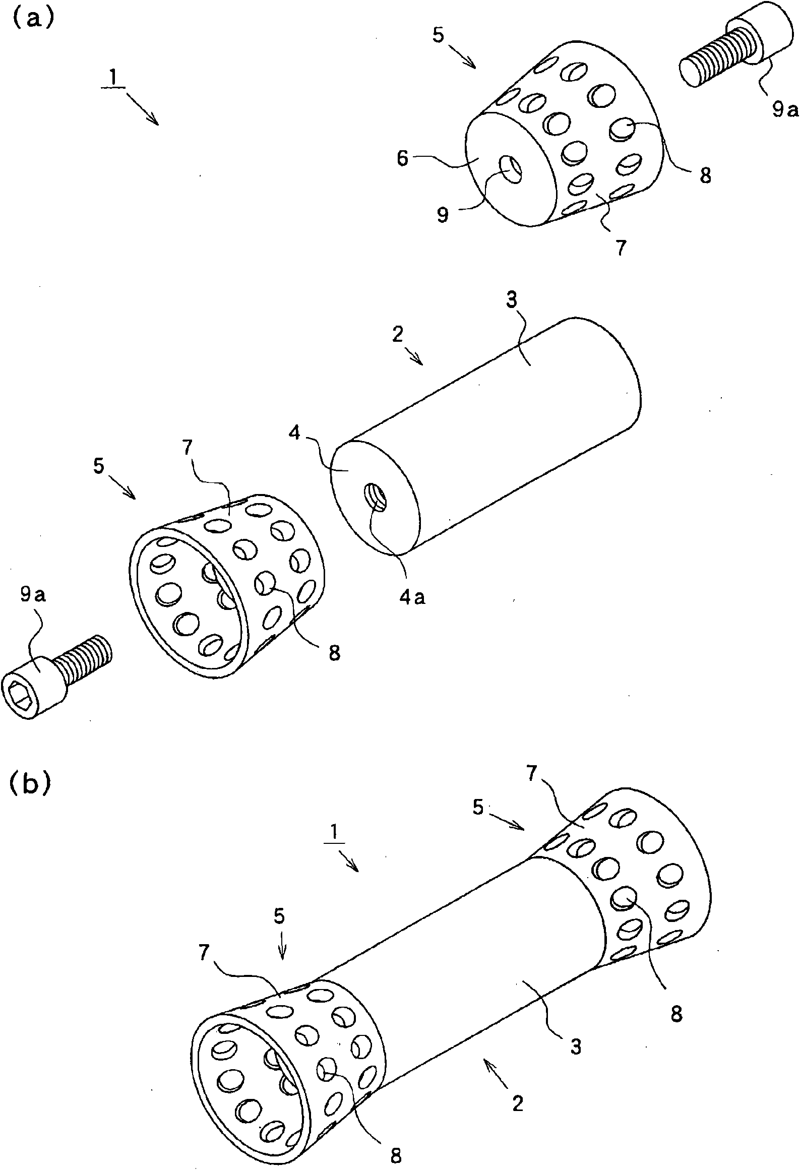
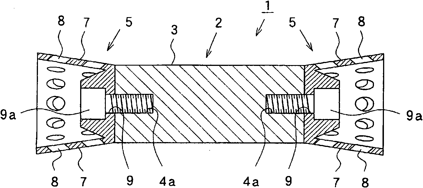
[0142] figure 1 (a) is an exploded perspective view of the magnetic field forming device for active water according to Embodiment 1 of the present invention, (b) is a perspective view of the magnetic field forming device for active water, figure 2 It is a sectional view of the main part of the magnetic field forming device for active water.

[0143] figure 1 , figure 2 Among them, 1 is the magnetic field forming device for active water according to Embodiment 1 of the present invention, 2 is a magnet formed into a round bar shape by using a rare earth cobalt magnet, etc., 3 is a side surface of the magnet 2, 4 is an end face of the magnet 2, and 4a is a magnet on the surface of the magnet 2. The bolt hole portion formed by the end face 4 of the steel pipe is made of non-magnetic materials such as aluminum alloy, copper alloy, titanium alloy, nickel-chromium-iron heat-resistant and corrosion-resistant alloy (Inconel), stainless steel, high manganese steel, synthetic resin, ...

Embodiment approach 2

[0175] Figure 8 It is a perspective view of the magnetic field forming device for active water of Embodiment 2, Figure 9 (a) is a perspective view seen from the slope part side of the guide member of the magnetic field forming tool for active water of the modification of Embodiment 2, (b) is a perspective view seen from the base part side. In addition, the same parts as those described in Embodiment 1 are denoted by the same reference numerals, and description thereof will be omitted.

[0176] Figure 8 Among them, 1a is the active water magnetic field forming device of Embodiment 2 of the present invention, 2 is a magnet, and 3 is the side of the magnet 2, and 5a is made of aluminum alloy, copper alloy, titanium alloy, nickel-chromium-iron heat-resistant and corrosion-resistant alloy, The guide member formed of non-magnetic materials such as stainless steel, high manganese steel, synthetic resin, inorganic material, etc., 6a is a base part formed in a cylindrical shape an...

Embodiment approach 3

[0183] Figure 10 is a sectional view of main parts of a fluid processing device according to Embodiment 3 of the present invention, Figure 11It is a cross-sectional view of main parts of a modified example of the fluid processing device of the third embodiment. In addition, the same parts as those described in Embodiment 1 are denoted by the same reference numerals, and description thereof will be omitted.

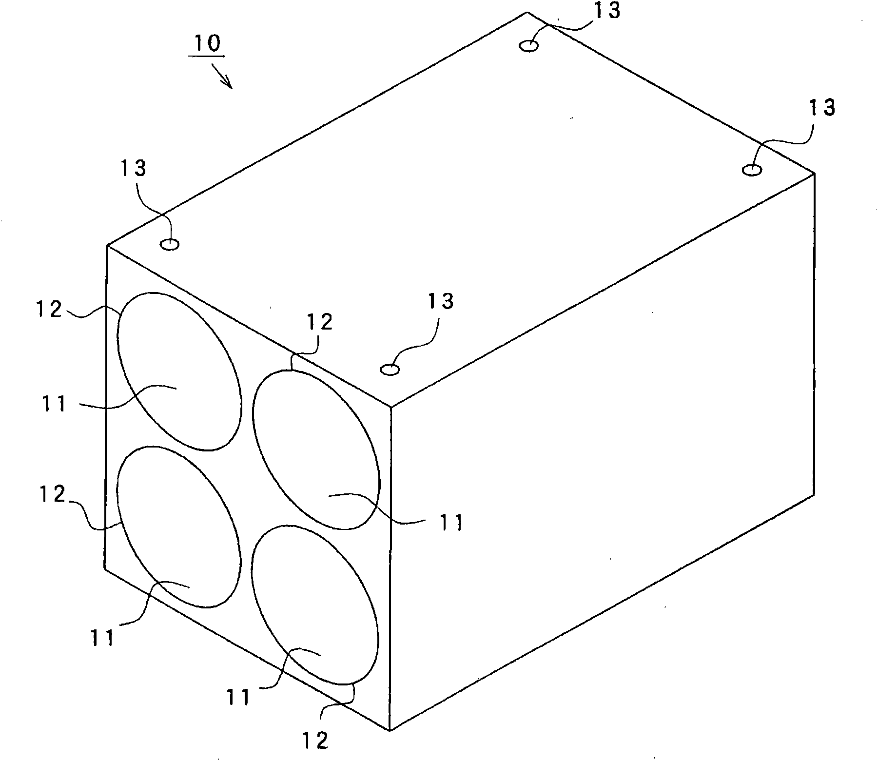
[0184] Figure 10 Among them, 41 is the fluid processing device of Embodiment 3, and 42 is formed of light-weight and less-corroded materials such as titanium alloy, nickel-chromium-iron heat-resistant and corrosion-resistant alloy, stainless steel, high-manganese steel, synthetic resin, and inorganic materials. Opened rectangular parallelepiped bottomed box-shaped, and the processing chamber of the fluid processing device 41 with two casings 10 containing four magnets 2 placed side by side at the bottom, 43 is placed on the casings 10, 10 placed side by side 44 is a ...


PUM


Abstract

An object of the present invention is to provide a magnetic field forming device for active water capable of uniformly forming a high magnetic field free from any unevenness in its intensity, activating a fluid regardless of the orientation of magnetic polarity of the magnets, bringing about excellent assembling efficiency not requiring assembling while checking the orientation of the magnets, being manufactured at a high product yield ratio without occurrence of defective products resulting from a difference in the orientation of the magnets, remarkably easily taking out the magnets without use of any exclusive special tool, and removing rust and stains adhered to the magnets by wiping off the magnets one by one, the maintenance efficiency of which is excellent. The magnetic field formingdevice for active water in which a flow path of a fluid is formed in a through hole, and the same magnetic field forming device includes a rod-shaped magnet 2 disposed with predetermined spacing fromthe inner wall of the through hole and having a fluid flow path formed between the inner wall and the side 3; a guide member 5 adhered to and fixed to the end part of the magnet 2, which is insertedinto the interior of the through hole; and a communication portion 8 formed at the guide member 5, which communicates with the fluid flow path.

Description

technical field [0001] The present invention relates to a magnetic field forming device for active water for activating fluid through a magnetic field and a fluid treatment device using the same. Background technique [0002] Conventionally, a fluid processing device is used in which a rod-shaped permanent magnet is arranged in a pipe to magnetically treat a fluid flowing in the pipe. [0003] The prior art of such a fluid treatment device discloses in (Patent Document 1) "a water activation device which makes the magnetic pole configurations different from each other on the side faces of the opposing magnets separated by a predetermined interval, and flows through The water between the sides of the facing magnets (the water passage) is magnetically treated to activate it." [0004] Patent Document 1: (Japanese) Unexamined Patent Publication No. 2001-340867 [0005] However, in the above-mentioned prior art, there are the following problems: [0006] (1) The water flowing...

Claims


Application Information

Patent Timeline
Patent Type & Authority Applications(China)
IPC IPC(8): C02F1/48
CPCC02F1/481C02F1/006C02F2303/14C02F1/48C02F2201/48
Inventor 山崎纯一
Owner TOKO KABUSHIKI KAISHA
Why Eureka
Try Eureka