
Missile-borne thermal battery activation device

A technology for activating device and thermal battery, applied in primary battery, primary battery use/maintenance, circuit, etc., can solve the problems of large space occupied by the firing mechanism, heavy weight, and large pulling force, etc. Low cost and simple assembly effect

Active Publication Date: 2020-09-08
NANJING UNIV OF SCI & TECH
View PDF3 Cites 0 Cited by
  • Summary
  • Abstract
  • Description
  • Claims
  • Application Information

AI Technical Summary

Problems solved by technology

There are two commonly used thermal battery activation methods. The first is to activate the thermal battery by relying on external power supply or high-pressure gas. The volume is too large and the structure is bloated; the second is to use a hole-shaped structure to connect the firing pin to the safety pin. The problem with this method is that the force required to remove the safety pin is relatively large, and it is not suitable for low launch overload environments. In addition, it is time-consuming and labor-intensive to align the head of the safety pin with the hole where the firing pin is inserted during the assembly process. At the same time, the firing mechanism takes up a lot of space and is heavy.

Method used


Image

  • Missile-borne thermal battery activation device
  • Missile-borne thermal battery activation device
  • Missile-borne thermal battery activation device

Examples


Embodiment Construction

[0017] The present invention will be further introduced below in conjunction with the accompanying drawings and specific embodiments.

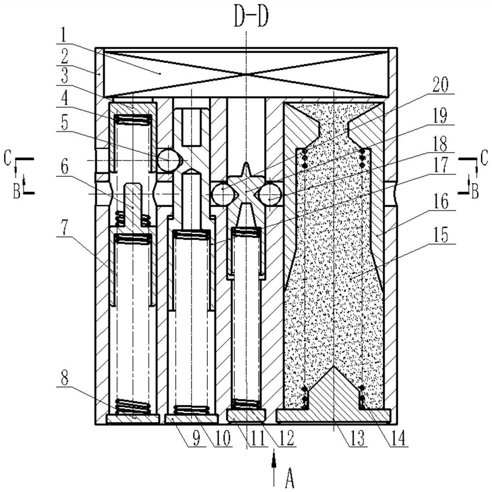
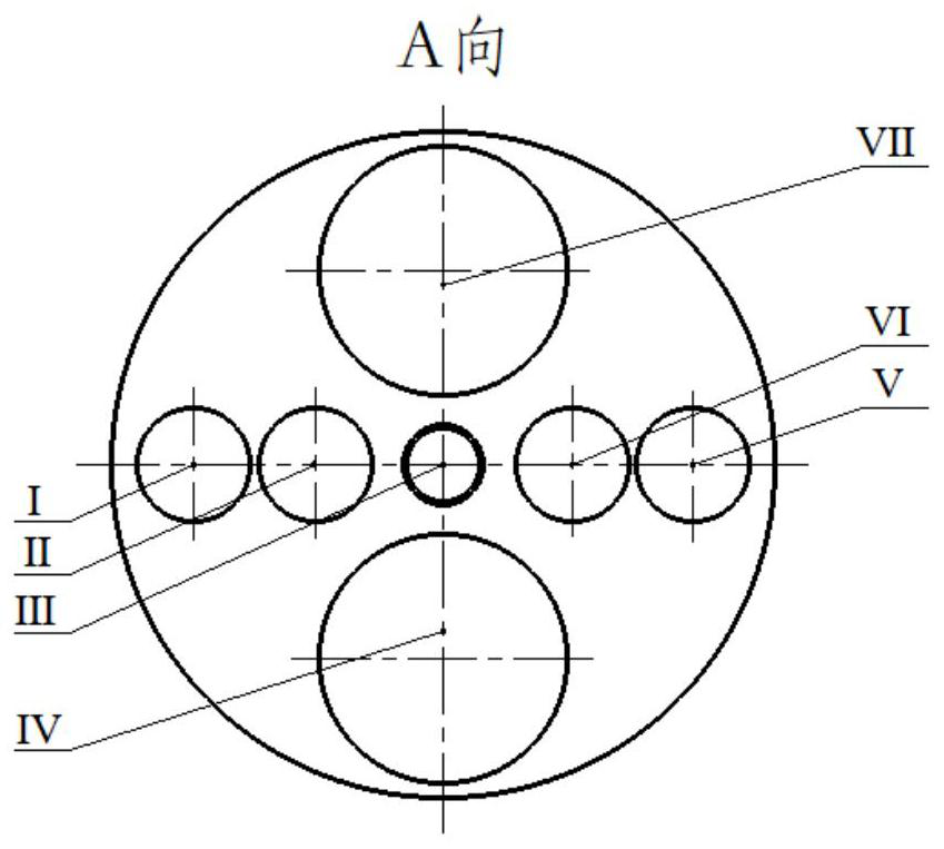
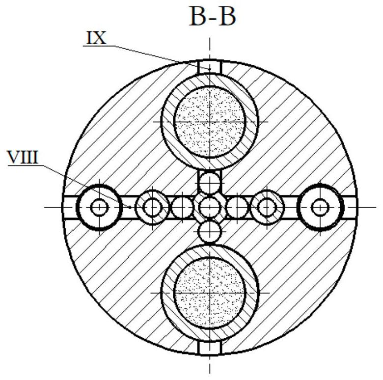
[0018] combine Figure 1-Figure 4 , a bomb-borne heat battery activation device of the present invention, its safety mechanism is two sets of two sets of parallel connection, respectively, a two-degree-of-freedom recoil safety mechanism and a quasi-fluid recoil safety mechanism, specifically including a heat battery 1, a body 2, and a firing mechanism , Two sets of dual-degree-of-freedom recoil safety mechanisms and two sets of quasi-fluid recoil safety mechanisms;

[0019] The firing mechanism includes a plug 11, a firing pin spring 12; a firing pin 19;

[0020] The two-degree-of-freedom recoil safety mechanism includes an upper inertia cylinder 3, an upper inertia spring 4, a safety ball I5, a lower inertia cylinder 6, a lower inertia spring 7, a bottom cover 8; a blocking block 9, an inertia pin spring 10, and an inertia pin 17;

[0021] ...


PUM

PropertyMeasurementUnit
Diameteraaaaaaaaaa

Abstract

The invention discloses a missile-borne thermal battery excitation device which comprises a body, a thermal battery arranged on the body, a firing mechanism, two sets of two-degree-of-freedom recoil safety mechanisms and two sets of quasi-fluid recoil safety mechanisms. Each two-degree-of-freedom recoil safety mechanism comprises an upper inertia cylinder, an upper inertia spring, a first safety ball, a lower inertia cylinder, a lower inertia spring, a bottom cover, a blocking block, an inertia pin spring and an inertia pin; each quasi-fluid recoil safety mechanism comprises a bottom plug, a large inertia spring, a quasi-fluid, a piston, a second safety device and a third safety ball; the firing mechanism is arranged in a cavity of the body; the upper inertia cylinder, the upper inertia spring, the lower inertia cylinder, the lower inertia spring and the bottom cover are sequentially connected in series; the inertia pin, the inertia pin spring and the blocking block are sequentially connected in series; the piston, the quasi-fluid and the bottom plug are sequentially connected in series; the first safety ball is located in a blind hole between the upper inertia cylinder and a V-shaped groove in the outer wall of the inertia pin; the second safety ball is clamped with the firing mechanism; and the third safety ball is clamped with the firing mechanism. The device is good in safety.

Description

technical field [0001] The invention belongs to the technical field of pyrotechnic batteries, in particular to an activation device for bomb-loaded thermal batteries. Background technique [0002] With the rapid development of computer technology, detection and guidance technology and artificial intelligence technology, modern weapons and equipment have achieved unprecedented development. These high-tech weapons and equipment have promoted the rapid development of thermal battery technology, making the application of thermal batteries more and more extensive. There are two commonly used thermal battery activation methods. The first is to activate the thermal battery by relying on external power supply or high-pressure gas. The volume is too large and the structure is bloated; the second is to use a hole-shaped structure to connect the firing pin to the safety pin. The problem with this method is that the force required to remove the safety pin is relatively large, and it is ...

Claims


Application Information

Patent Timeline
IPC IPC(8): H01M6/38H01M6/50
CPCH01M6/38H01M6/5088
Inventor 王雨时居荣誉王光宇闻泉张志彪
Owner NANJING UNIV OF SCI & TECH
Learn More