Lamp source heat-dissipating module for street lamp and heat sink thereof

A heat dissipation module and heat sink technology, which is applied to the cooling/heating device, circuit, light source, etc. of the lighting device, and can solve the problems of poor heat dissipation of the heat dissipation module, large and complex radiator structure, etc.

Inactive Publication Date: 2010-03-03
ACBEL POLYTECH INC
View PDF0 Cites 2 Cited by
  • Summary
  • Abstract
  • Description
  • Claims
  • Application Information

AI Technical Summary

Problems solved by technology

The structural design of this heat dissipation module, because the LED light source and the heat sink group are connected by heat pipes, and the heat sink group is the main heat dissipation component, so the waste heat generated by the LED light source cannot be directly conducted to the heat sink group, so this cooling module still has the disadvantage of poor heat dissipation
[0004] Another example is the utility model patent of Taiwan Announcement No. 320642 "LED Street Light Heat Dissipation Structure", and refer to Figure 11 As shown, it also uses a heat pipe 601 to connect the cooling fins 60 and multiple LED light sources 61. In order to improve the cooling effect of this utility model patent, the cooling fins 60 are arranged on the lamp post 62 of the street lamp, that is, on the lampshade 63, the heat dissipation speed of the heat dissipation fins 60 is increased; however, this heat dissipation structure is still the same as the previous utility model patent, and the heat dissipation fins cannot be directly connected to the LED light source, so the waste heat cannot be quickly transferred to the heat dissipation fins a
[0005] As China Taiwan Announcement No. 314825 "LED Heat Dissipation Structure and Street Lamp with the LED Lamp Group Heat Dissipation Structure" utility model patent, please refer to Figure 12 and Figure 13 As shown, it includes a plurality of heat dissipation units 70, a plurality of LED light sources 71, a base 72 and a cover 73, wherein each LED light source 71 is arranged in the heat dissipation fins 701 of the corresponding heat dissipation unit 70, and the heat dissipation unit 70 and the LED light source 71 are interposed between the base 72 and the cover body 73. Since the cooling fin 701 is a cylindrical cooling fin with radially extending fins, the LED light source 71 can be accommodated in the In the cylindrical fins 701, the waste heat generated by the LED light source can be directly and quickly transferred to the fins for heat dissipation; however, the structure size of the radiator is larger and more complicated than the aforementioned two utility model patents

Method used


Image

  • Lamp source heat-dissipating module for street lamp and heat sink thereof
  • Lamp source heat-dissipating module for street lamp and heat sink thereof
  • Lamp source heat-dissipating module for street lamp and heat sink thereof

Examples


Embodiment Construction

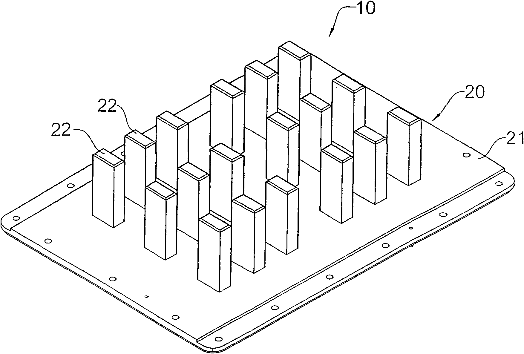
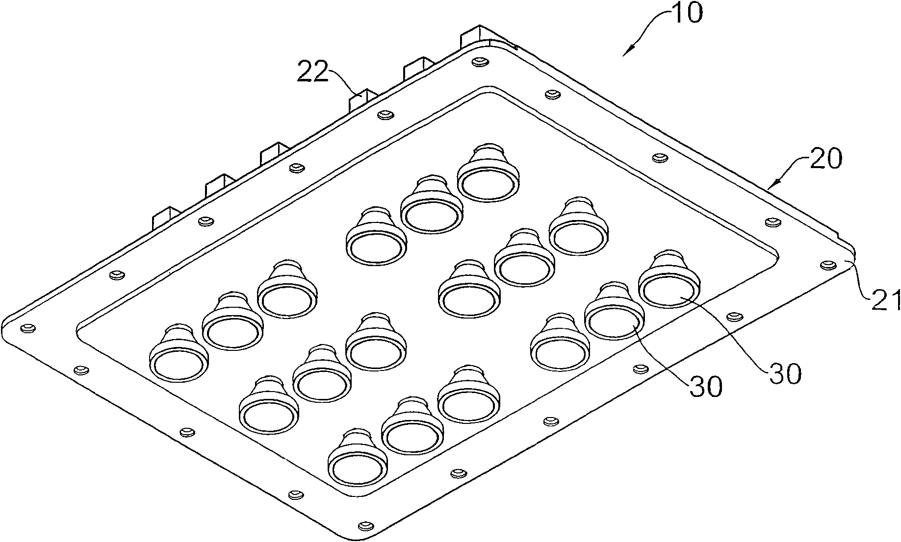
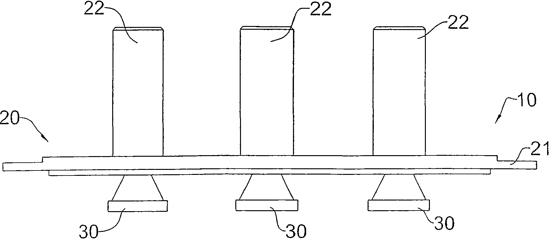
[0037] see figure 1 , figure 2 , Figure 3A and Figure 4 As shown, it is a preferred embodiment of the light source cooling module 10 of the present invention, which includes:

[0038] A heat sink 20, which includes a flat heat-conducting substrate 21 and a plurality of main thermal columns 22 extending integrally upward from the top surface of the heat-conducting substrate 21; in this embodiment, the plurality of main thermal columns 22 are arranged in a matrix; and

[0039] A plurality of point heat sources 30 are arranged on the bottom surface of the heat-conducting substrate 21, wherein each point heat source 30 is facing the position of the leading heat column 22 on the opposite top surface, so that the heat of the point heat source 30 is quickly dissipated outward by the leading heat column 22; In this embodiment, each point heat source 30 is an LED light source, and the LED light source constitutes a heat source when turned on.

[0040] Since the heat-conducting...


PUM


Abstract

The invention relates to a lamp source heat-dissipating module for a street lamp and a heat sink thereof. The lamp source heat-dissipating module comprises the heat sink and a plurality of point heatsources; a plurality of main heat-conducting posts are upwards integrated on the top surface of a flat heat-conducting base plate to form the heat sink; the point heat sources are directly arranged onthe bottom surface of the heat-conducting base plate; and moreover, the point heat sources face the positions of the main heat-conducting posts of the opposite top surface. Consequently, the intenseheat of the middle of each point heat source can be quickly dissipated by the main heat-conducting posts; moreover, because the main heat-conducting posts are integrated with the heat-conducting baseplate, the thermal resistance of the joint in between is the lowest, and the heat of the point heat sources can be quickly transferred to the main heat-conducting posts above; and therefore, the heat-dissipating effect is enhanced.

Description

technical field [0001] The invention relates to a light source heat dissipation module used for street lamps, in particular to a light source heat dissipation module with good heat dissipation effect and its heat sink. Background technique [0002] In view of the increasingly depleted energy sources, saving energy is no longer a slogan, but an action that must be practiced by the whole people. In addition to personal electricity consumption, the electricity consumption of public facilities (such as street lights) serving the public is even more alarming. Therefore, we are looking for more energy-saving The light source of electric energy will be very helpful for greatly reducing the power consumption of public lighting equipment such as street lights. [0003] At present, the most popular energy-saving lamps are LED light sources. Therefore, the government has eliminated some old street lamps and replaced them with new energy-saving LED street lamps in implementing the energ...

Claims


Application Information

Patent Timeline
Patent Type & Authority Applications(China)
IPC IPC(8): F21V29/00H01L23/367F21W131/103F21Y101/02F21V29/70
CPCY02B20/72
Inventor 李哲纶许清闵陈荣发朱俊杰
Owner ACBEL POLYTECH INC
Why Eureka
Try Eureka