Conveying pipe, concrete conveying machine and method for manufacturing conveying pipe

A conveying pipe and concrete technology, applied in the field of conveying pipes, can solve the problems such as the inability to realize the life design of the inner pipe of the conveying pipe, the high power consumption of the concrete conveying machinery, the inability to realize the life design of the conveying pipe, etc., and achieves light weight and small friction coefficient. , the effect of enhancing strength

Inactive Publication Date: 2010-03-03
SANY HEAVY IND CO LTD (CN)
View PDF0 Cites 9 Cited by
  • Summary
  • Abstract
  • Description
  • Claims
  • Application Information

AI Technical Summary

Problems solved by technology

Conveyor pipes with a large weight will lead to a large power consumption of the concrete conveying machinery, which is not conducive to the energy saving of the concrete conveying machinery
[0007] Second, it is easy to scale, thus reducing the efficiency of concrete delivery
Since the inner pipe is made of metal materials, the concrete is easy to stick to the inner pipe, and then scales will form in the delivery pipe, especially in the delivery bend, which will reduce the delivery efficiency of the concrete; in severe cases, it may also cause the delivery pipe to be blocked.
[0008] Third, the safety performance is low
The failure form of the existing conveying pipe is the burst failure after the pipe wall is thinned, and the sudden burst failure can easily cause a safety accident
[0009] Fourth, the equal-life design in the delivery pipe cannot be realized
Due to the needs of installation and assembly, the inner tubes in the delivery pipes in the prior art cannot be designed with different thicknesses according to the wear speed of each part, so that the equal life design of the inner tubes of the delivery tube cannot be realized; this not only causes material waste, but also Shorten the maintenance cycle of the delivery pipe

Method used


Image

  • Conveying pipe, concrete conveying machine and method for manufacturing conveying pipe
  • Conveying pipe, concrete conveying machine and method for manufacturing conveying pipe
  • Conveying pipe, concrete conveying machine and method for manufacturing conveying pipe

Examples


Embodiment 1

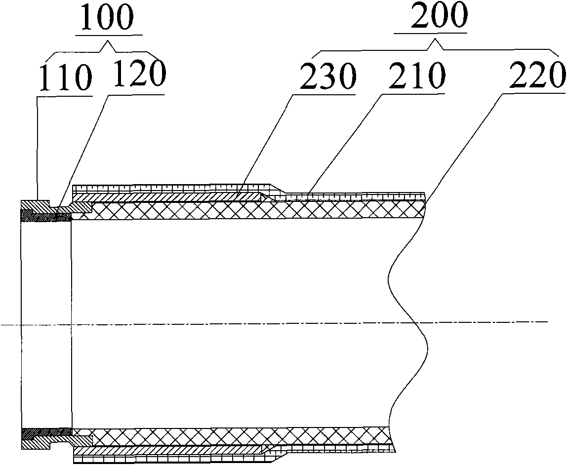
[0042] The delivery pipe provided in Embodiment 1 includes a nozzle section 100 and a pipe body 200; a flange structure can be provided on the nozzle section 100 to realize a reliable connection between the delivery pipes; the inner end of the nozzle section 100 and the pipe body 200 The ends are fixed. The pipe body 200 includes a pipe wall 210 and an inner lining 220 located in the pipe wall 210; the pipe wall 210 is made of a composite material, and the composite material is composed of resin and fiber. Of course, it can also be made in a composite material according to actual needs Add other materials to make the composite material have predetermined characteristics to meet actual needs. Liner 220 is made of ultra high molecular weight polyethylene.

[0043] like figure 1 As shown, in order to ensure the reliability of fixing the nozzle section 100 and the pipe body 200 , and further ensure the reliability of the conveying pipe to transport concrete, in this example, the...

Embodiment 2

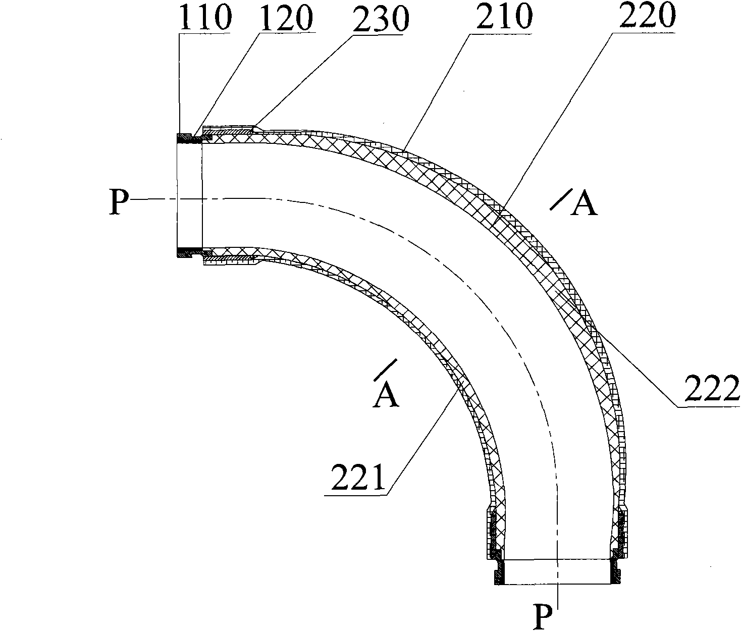
[0060] The basic structure of a delivery elbow provided by Embodiment 2 is the same as that of Embodiment 1, including a nozzle section 100 , a pipe body 200 , and the pipe body includes a pipe wall 210 , a lining 220 and a connecting plate 230 .

[0061] As shown, in this example, the thickness of the various parts of the liner 220 is not the same. In the transverse section, the thickness of the inner arc portion 221 of the lining 220 is smaller than the thickness of the outer arc portion 222 thereof. In this way, under the same condition of the inner liner 220 wear and wear resistance, the wear rate of the outer arc portion 222 is greater than the wear rate of the inner arc portion 221, because the thickness of the outer arc portion 222 is greater than the thickness of the inner arc portion 221, so it can be reduced. The gap between the service life of the small inner arc part 221 and the outer arc part 222; as image 3 As shown, the preferred technical solution is that, in...


PUM


Abstract

The invention discloses a conveying pipe used for conveying concrete, a concrete conveying machine provided with the conveying pipe, and a method for manufacturing the conveying pipe. The conveying pipe comprises a pipe orifice section and a pipe body, wherein the inner end of the pipe orifice section is fixed with the end part of the pipe body; the pipe wall of the pipe body is made of compositematerial which comprises resin and fiber; and the pipe wall is internally provided with an inner lining made of ultra high molecular weight polyethylene. The conveying pipe provided by the invention not only can meet the need of conveying the concrete and has the characteristics of the conveying pipe in the prior art, but also can reduce the energy consumption of the concrete conveying machine dueto the extremely light weight; as the inner lining has stronger self-lubricating performance and less friction coefficient, the fouling of the conveying pipe can be reduced, the flow resistance of the concrete is less, the conveying efficiency of the concrete is improved, and the power consumption of a concrete pump is lowered; and furthermore, the invention also can avoid the safety accidents caused by pipe explosion and improve the safety of the conveying pipe.

Description

technical field [0001] The invention relates to a wear-resistant and pressure-resistant conveying pipe technology, in particular to a conveying pipe for conveying concrete, a concrete conveying machine with the conveying pipe, and a manufacturing method of the conveying pipe. Background technique [0002] Currently, concrete pumps are generally used to deliver concrete during construction operations. In the process of conveying concrete, the concrete pump provides appropriate power to make the concrete slurry reach the predetermined place through the conveying pipeline under appropriate pressure, so as to perform concrete pouring or pouring operations at a position far away from the mixing station. The conveying pipeline is formed by connecting several conveying pipes in sequence. [0003] In the process of conveying concrete, on the one hand, the inner wall of the conveying pipe has to bear the continuous erosion and wear caused by the flow of concrete mud; When transport...

Claims


Application Information

Patent Timeline
IPC IPC(8): F16L11/04F16L58/04F04B15/02
Inventor 蒋建军何正华于国亮朱小平
Owner SANY HEAVY IND CO LTD (CN)
Why Eureka
Try Eureka