
Green phosphor powder excited by vacuum ultraviolet and low-voltage cathode ray and preparation method thereof

A green phosphor and cathode ray technology, applied in the field of phosphor materials, can solve problems such as the influence of afterglow time, poor stability of PDP screen picture quality, and short afterglow time, and achieve low cost, easy operation, and strong green light emission Effect

Inactive Publication Date: 2013-09-04
SUN YAT SEN UNIV
View PDF0 Cites 0 Cited by
  • Summary
  • Abstract
  • Description
  • Claims
  • Application Information

AI Technical Summary

Problems solved by technology

[0006] The purpose of the present invention is to overcome the problem that the existing fluorescent powder has too long afterglow time, which affects the quality of the PDP screen picture and the stability of the FED fluorescent powder under electron bombardment, and provides a high emission intensity, short afterglow time and high stability. Green Phosphors for Vacuum Ultraviolet and Low-Voltage Cathode Ray Excitation

Method used


Image

  • Green phosphor powder excited by vacuum ultraviolet and low-voltage cathode ray and preparation method thereof
  • Green phosphor powder excited by vacuum ultraviolet and low-voltage cathode ray and preparation method thereof
  • Green phosphor powder excited by vacuum ultraviolet and low-voltage cathode ray and preparation method thereof

Examples


Embodiment 1

[0022] Weigh lanthanum trioxide (La 2 o 3 )0.5404g, terbium oxide (Tb 4 o 7 ) 0.0031g, calcium carbonate (CaCO 3 ) 1.0009g, sodium carbonate (Na 2 CO 3 ) 0.1943g, ammonium dihydrogen phosphate (NH 4 h 2 PO 4 ) 1.1504g, ammonium fluoride (NH 4 F) 0.1729g, fully ground in an agate mortar and mixed evenly, sintered in a carbon monoxide atmosphere at 1050°C for 4 hours, cooled to room temperature, and the sample was taken out and ground to finally obtain the product.

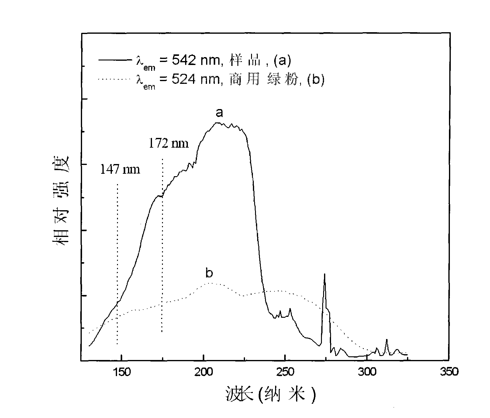
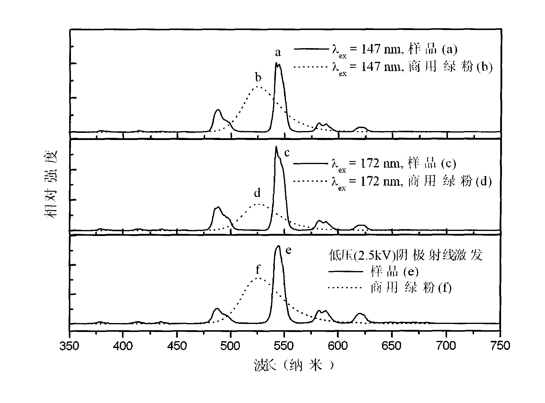
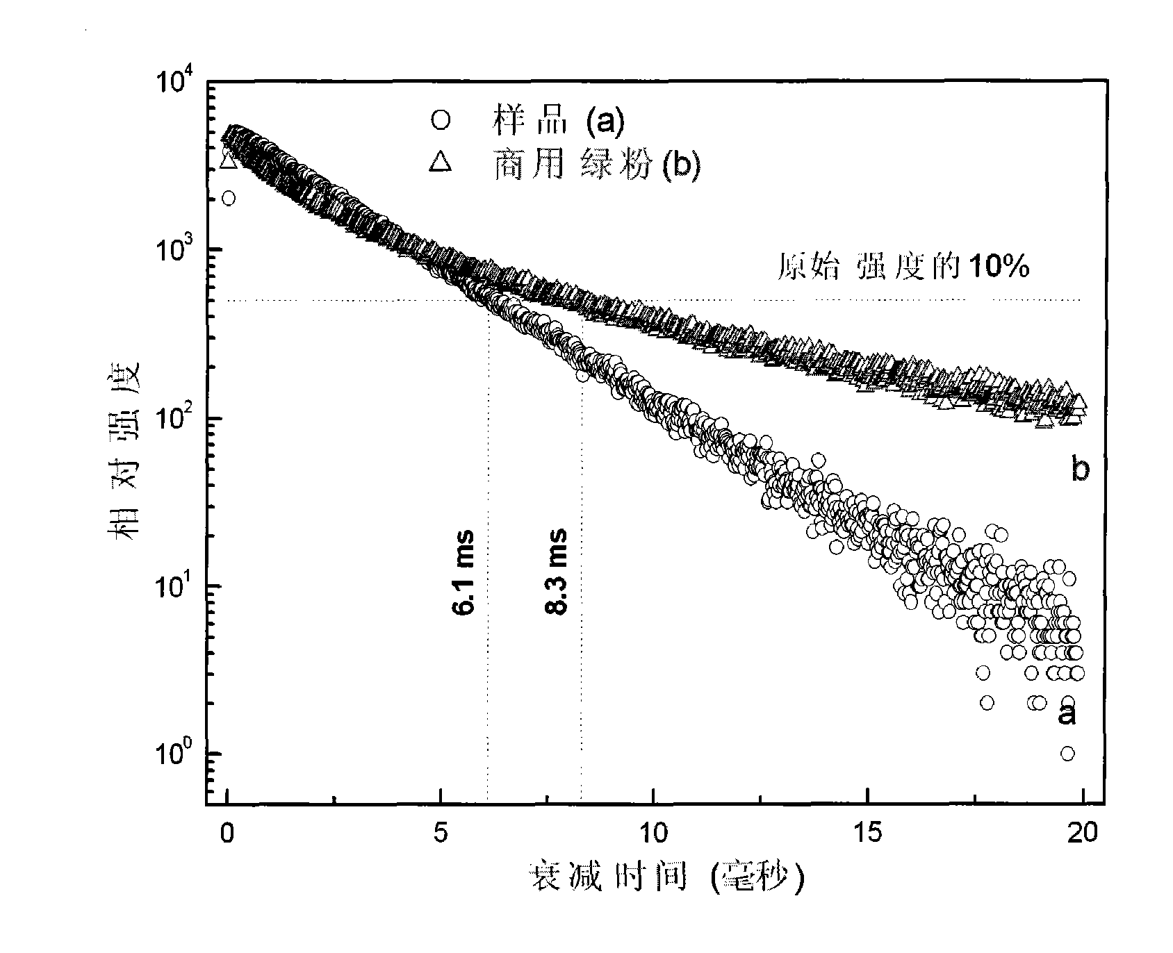
[0023] The fluorescent powder (monitoring 542nm) that embodiment 1 makes and current commercial PDP green fluorescent powder Zn 2 SiO 4 :Mn 2+ (monitoring 524nm) excitation spectrum is shown as figure 1 shown by figure 1 It can be seen that the phosphor has strong absorption at 147nm and 172nm, especially at 172nm, which is much stronger than that of Zn 2 SiO 4 :Mn 2+ , which shows that the fluorescent powder of Example 1 is in good agreement with the vacuum ultraviolet (VUV) light wavelength produce...

Embodiment 2

[0027] Weigh lanthanum trioxide (Gd 2 o 3 ) 0.6012g, terbium oxide (Tb 4 o 7 ) 0.0031g, calcium carbonate (CaCO 3 ) 1.0009g, sodium carbonate (Na 2 CO 3 ) 0.1943g, ammonium dihydrogen phosphate (NH 4 h 2 PO 4 ) 1.1504g, ammonium fluoride (NH 4 F) 0.1729g, fully ground in an agate mortar and mixed evenly, sintered in a carbon monoxide atmosphere at 1050°C for 4 hours, cooled to room temperature, and the sample was taken out and ground to finally obtain the product.

Embodiment 3

[0029] Weigh two lanthanum trioxide (Y 2 o 3 )0.3745g, terbium oxide (Tb 4 o 7 ) 0.0031g, calcium carbonate (CaCO 3 ) 1.0009g, sodium carbonate (Na 2 CO 3 ) 0.1943g, ammonium dihydrogen phosphate (NH 4 h 2 PO 4 ) 1.1504g, ammonium fluoride (NH 4F) 0.1729g, fully ground in an agate mortar and mixed evenly, sintered in a carbon monoxide atmosphere at 1050°C for 4 hours, cooled to room temperature, and the sample was taken out and ground to finally obtain the product.


PUM

PropertyMeasurementUnit
fluorescence lifetimeaaaaaaaaaa

Abstract

The invention discloses a green phosphor powder excited by vacuum ultraviolet and low-voltage cathode ray and a preparation method thereof; the green phosphor powder has the chemical formula of M6 Ln(2-x) Tbx R2 (PO4)6 F2; wherein M is at least one of alkaline earth metal ions such as Ca<2+>, Sr<2+> and Ba<2+>; Ln is rare earth metal ion selected from La<3+>, Gd<3+> and Y<3+>; R is alkaline earth metal ion selected from Na<+> and K<+>; x is mole percent coefficient of doped element Tb relative to the rare earth element of Ln, and 0.005<=x<=0.90; and main luminous ion is Tb<3+>. Rare earth oxide, ammonium dihydrogen phosphate, alkaline earth metal carbonate and ammonium fluoride are evenly mixed together and then sintered and ground in carbon monoxide atmosphere. The material can effectively absorb green emission which is positioned at the place of 542nm and generated by vacuum ultraviolet within the distance of 147nm and 172nm, and the intensity of emission and the fluorescence lifetime that are excited from the distance of 172nm are superior to those of green powder Zn2 SO4: Mn<2+>. Stronger green light also can be generated under the excitation of the low-voltage cathode ray. The rare earth green phosphor powder has high luminous intensity and color purity, short persistence and good stability, so as to be suitable for being taken as green emitting luminescent material of PDP and FED.

Description

technical field [0001] The invention relates to a fluorescent powder material. Background technique [0002] Plasma Display Panel (PDP for short) is currently the main large-screen display technology. PDP is a kind of three-color fluorescent powder that is excited by ultraviolet rays (mainly at 147 nanometers (nm) and 172 nanometers (nm)) generated by plasma discharge of a xenon (Xe)-based rare gas mixture under the control of a drive circuit. Flat panel display technology. [0003] Field emission display technology is a flat-panel display technology newly developed by (FED) in recent years. Its working principle is similar to that of traditional CRT display. However, unlike CRTs that control electron deflection through electromagnetic fields, FEDs emit electrons in a planar manner without deflection coils, which allows FEDs to be made into very thin flat panel displays. FED has potential advantages in brightness, viewing angle, response time, operating temperature range,...

Claims


Application Information

Patent Timeline
Patent Type & Authority Patents(China)
IPC IPC(8): C09K11/86
Inventor 梁宏斌谢木标韩冰陈万平苏锵
Owner SUN YAT SEN UNIV
Learn More