Marine oil-water separator and separation method thereof

An oil-water separator and boat technology, applied in separation methods, liquid separation, ships, etc., can solve the problems of large area, polluted water resources, complicated machine connection, etc., to save boat space, achieve effective utilization, The effect of uniform heat transfer

Active Publication Date: 2009-12-09
无锡强工机械工业有限公司
View PDF0 Cites 5 Cited by
  • Summary
  • Abstract
  • Description
  • Claims
  • Application Information

AI Technical Summary

Problems solved by technology

[0002] Ships and submarines will burn raw materials and discharge oily wastewater during navigation. The oily wastewater in the bilge of ships sometimes has an oil content as high as 2000ppm. If it is discharged directly, it will seriously pollute water resources and bring great harm. Therefore, the implementation of Oil-water separation to remove the oil is very necessary. Most of the oil-water separation in the prior art is through gravity separation or gravity-coarse-graining-filtration combined separation. Although these separation methods can separate most of the dirty oil, but in the end The ppm value in the separated discharge water is still high, which is still far from the increasingly stringent environmental protection requirements. If a slanted plate sedimentation tower or a pre-filter is used, it will occupy a large area, the machine connection is complicated, and it can only work alone. If and If the general oil-water separator is connected in series, additional pipeline valves must be added, which is not suitable for installation and use in places with small spaces such as ships.

Method used


Image

  • Marine oil-water separator and separation method thereof

Examples


Embodiment Construction

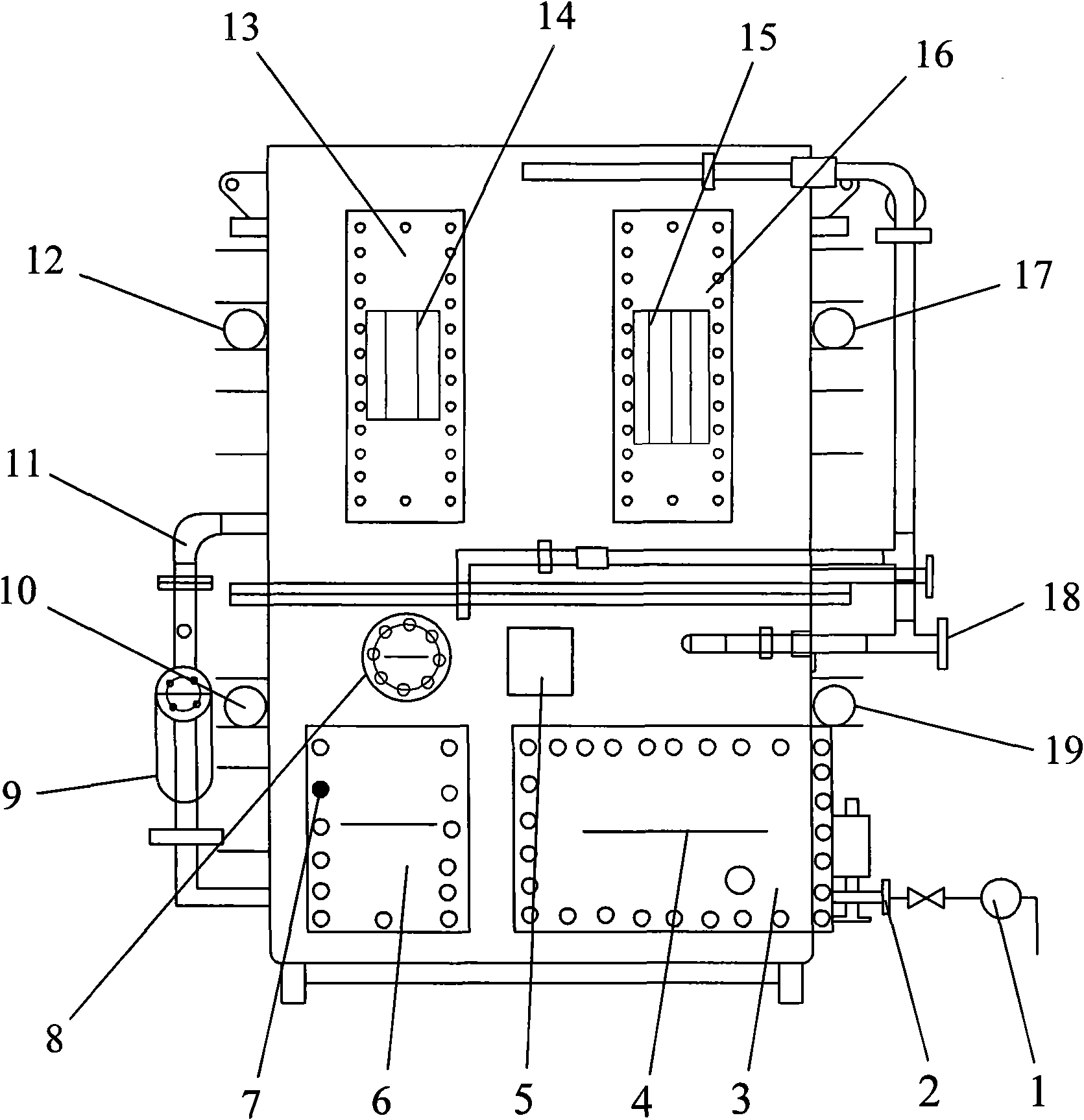
[0017] The present invention will be further described below in conjunction with specific drawings and embodiments.

[0018] Such as figure 1 As shown, the boat oil-water separator includes a box body with an inlet 2 and an outlet 18 installed on the side wall, the box is divided into four separation chambers, the inlet 2 communicates with the first separation chamber 3, and the first separation chamber The cavity 3 is equipped with an advection Brown inclined plate 4, the bottom is provided with a slag discharge port, and the upper part is provided with an oil discharge port A, and the oil discharge port A is controlled by the sensor A19 and the solenoid valve A5 installed on the outer wall of the first separation chamber 3 Opening and closing: the first separation chamber 3 communicates with the second separation chamber 6, a steam heating demulsification device 8 and a solid emulsifying agent 7 are installed in the second separation chamber 6, and an oil discharge port B is...


PUM


Abstract

The invention relates to a marine oil-water separator and a separation method thereof. The marine oil-water separator comprises a case body, the side wall of which is provided with an inlet and an outlet. The marine oil-water separator is characterized in that the case body is divided into four separation cavities, progressive separation and filtration is carried out, a first separation cavity carries out primary separation by an advection type Brown sloping plate, a second separation cavity carries out emulsion breaking by a steam heating emulsion breaking device and solid emulsion, a third separation cavity carries out filtration by a medium-grade filtration core and a fourth separation cavity carries out ultrafiltration by an ultrafiltration core; and the separation method of the marine oil-water separator comprises four steps of primary separation: primary separation, emulsion breaking, filtration and ultrafiltration. The oil-water separator has small volume and saves the space of a boat; the oil-water separator adopts the residual heat of an engine or other steam energy sources to work, a steam pipe is in a spiral type structure and has uniform and fast heat transfer, and the efficient utilization of energy sources is realized; and the content of oil in the bilge water of the boat after being processed by the four steps of primary separation, emulsion breaking, filtration and ultrafiltration is less than 3ppm and far exceeds an environmental protection emission standard stated by the international maritime organization.

Description

technical field [0001] The invention belongs to the technical field of oil-water separation treatment, in particular to an oil-water separator for boats and a separation method thereof. Background technique [0002] Ships and submarines will burn raw materials and discharge oily wastewater during navigation. The oily wastewater in the bilge of ships sometimes has an oil content as high as 2000ppm. If it is discharged directly, it will seriously pollute water resources and bring great harm. Therefore, the implementation of Oil-water separation to remove the oil is very necessary. Most of the oil-water separation in the prior art is through gravity separation or gravity-coarse-graining-filtration combined separation. Although these separation methods can separate most of the dirty oil, but in the end The ppm value in the separated discharge water is still high, which is still far from the increasingly stringent environmental protection requirements. If a slanted plate sediment...

Claims


Application Information

Patent Timeline
IPC IPC(8): C02F1/40B63J4/00
Inventor 强光初
Owner 无锡强工机械工业有限公司
Why Eureka
Try Eureka