Etching method

An etching rate and etching stop technology, applied in electrical components, semiconductor/solid-state device manufacturing, circuits, etc., can solve problems affecting device performance, etc., to reduce excessive etching, reduce etching rate, reduce The effect of the dent problem

Inactive Publication Date: 2009-12-02
SEMICONDUCTOR MANUFACTURING INTERNATIONAL (BEIJING) CORP
View PDF1 Cites 12 Cited by
  • Summary
  • Abstract
  • Description
  • Claims
  • Application Information

AI Technical Summary

Problems solved by technology

The recess 150 seriously affects the performance of the device in the manufactured device
[0007] The root depression problem of the above int...

Method used


Image

  • Etching method
  • Etching method
  • Etching method

Examples


Embodiment Construction

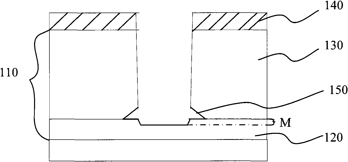
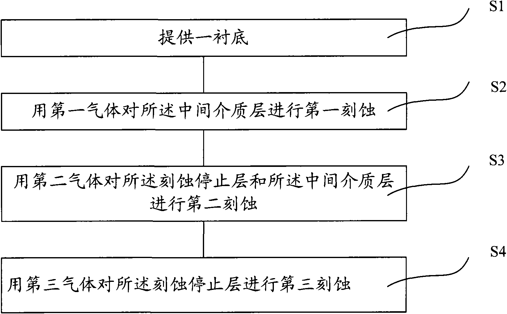
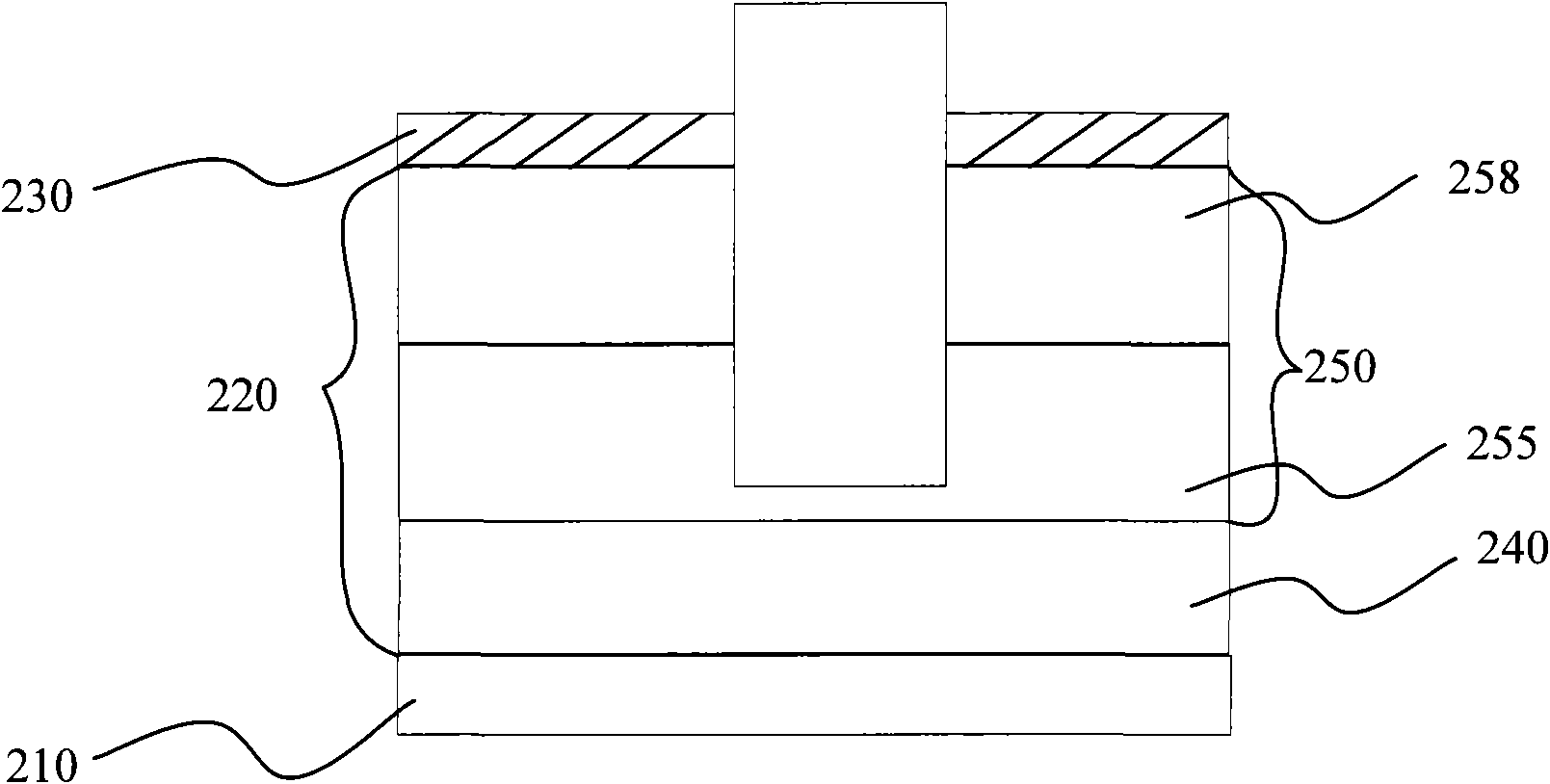
[0036] In order to make the above-mentioned purposes, features and advantages of the present invention more obvious and understandable, the specific implementation modes of the present invention will be described in detail below in conjunction with the accompanying drawings, so that the above-mentioned and other purposes, features and advantages of the present invention will be clearer. Like reference numerals designate like parts throughout the drawings. The drawings have not been drawn to scale, emphasis instead being placed upon illustrating the gist of the invention. In the drawings, the thickness of layers and regions are exaggerated for clarity.

[0037] For clarity, in the following description, well-known functions and constructions are not described in detail since they would obscure the invention with unnecessary detail. It should be appreciated that in the development of any actual embodiment, numerous implementation details must be worked out to achieve the develo...


PUM

PropertyMeasurementUnit
Power supplyaaaaaaaaaa

Abstract

The invention discloses an etching method, comprising: providing a substrate with a dielectric layer which comprises an etching stopping layer and a middle dielectric layer on the etching stopping layer; using a first gas to carry out a first etching on the middle dielectric layer and stopping the etching in the middle dielectric layer; using a second gas to carry out a second etching on the etching stopping layer and the middle dielectric layer and stopping the second etching in the etching stopping layer; and using a third gas to carry out a third etching on the etching stopping layer after the second etching, wherein, the etching speed rate of the third gas on the etching stopping layer is larger than the etching speed rate of the second gas on the etching stopping layer, and the etching speed rate of the third gas on the middle dielectric layer is smaller than the etching speed rate of the second gas on the middle dielectric layer. The technical scheme of the invention uses different etching gases to selectively etch the dielectric layer, thus reducing the root sinking of the middle dielectric layer after etching.

Description

technical field [0001] The invention relates to the technical field of semiconductor manufacturing, in particular to an etching method. Background technique [0002] VLSI usually requires more than one metal layer to provide sufficient interconnection capacity, so the interconnection between metal layers, the connection between the active area of ​​the device and the external circuit is through the via hole or trench filled with conductive material Realization, and in order to ensure the stability of the device, it is required that there is no electrical connection between the through hole or the trench, so it is very important to strictly control the etching process of the through hole. With increasing device density and process complexity, higher requirements are imposed on via and trench etching processes. [0003] At present, in semiconductor manufacturing, the traditional method of forming a contact hole is to etch the dielectric layer of the substrate, form a via hole...

Claims


Application Information

Patent Timeline
IPC IPC(8): H01L21/311H01L21/768
Inventor 王新鹏沈满华孙武尹晓明
Owner SEMICONDUCTOR MANUFACTURING INTERNATIONAL (BEIJING) CORP
Why Eureka
Try Eureka