
Rotational flow absorption filter concentration and separation technique and device thereof

A technology of adsorption filtration and process flow, which is applied in the direction of filtration separation, separation method, filtration circuit, etc. It can solve the problems of high chemical consumption in subsequent treatment, large area occupied by gravity concentration, poor concentration effect, etc., and achieve sludge concentration ratio High, less space occupation, easy to clean and replace

Inactive Publication Date: 2009-11-11
熊四达
View PDF0 Cites 26 Cited by
  • Summary
  • Abstract
  • Description
  • Claims
  • Application Information

AI Technical Summary

Problems solved by technology

[0006] The technical problem to be solved by the present invention is: in view of the limitations of the applicable scope of the known cyclone separation technology, the shortcomings of the known gravity concentration, such as large footprint, poor concentration effect, large capital investment, and high consumption of follow-up treatment chemicals, etc., to provide a method using Cyclone adsorption filtration concentration separation process and device combined with cyclone separation process and adsorption filtration

Method used


Image

  • Rotational flow absorption filter concentration and separation technique and device thereof
  • Rotational flow absorption filter concentration and separation technique and device thereof

Examples


Embodiment Construction

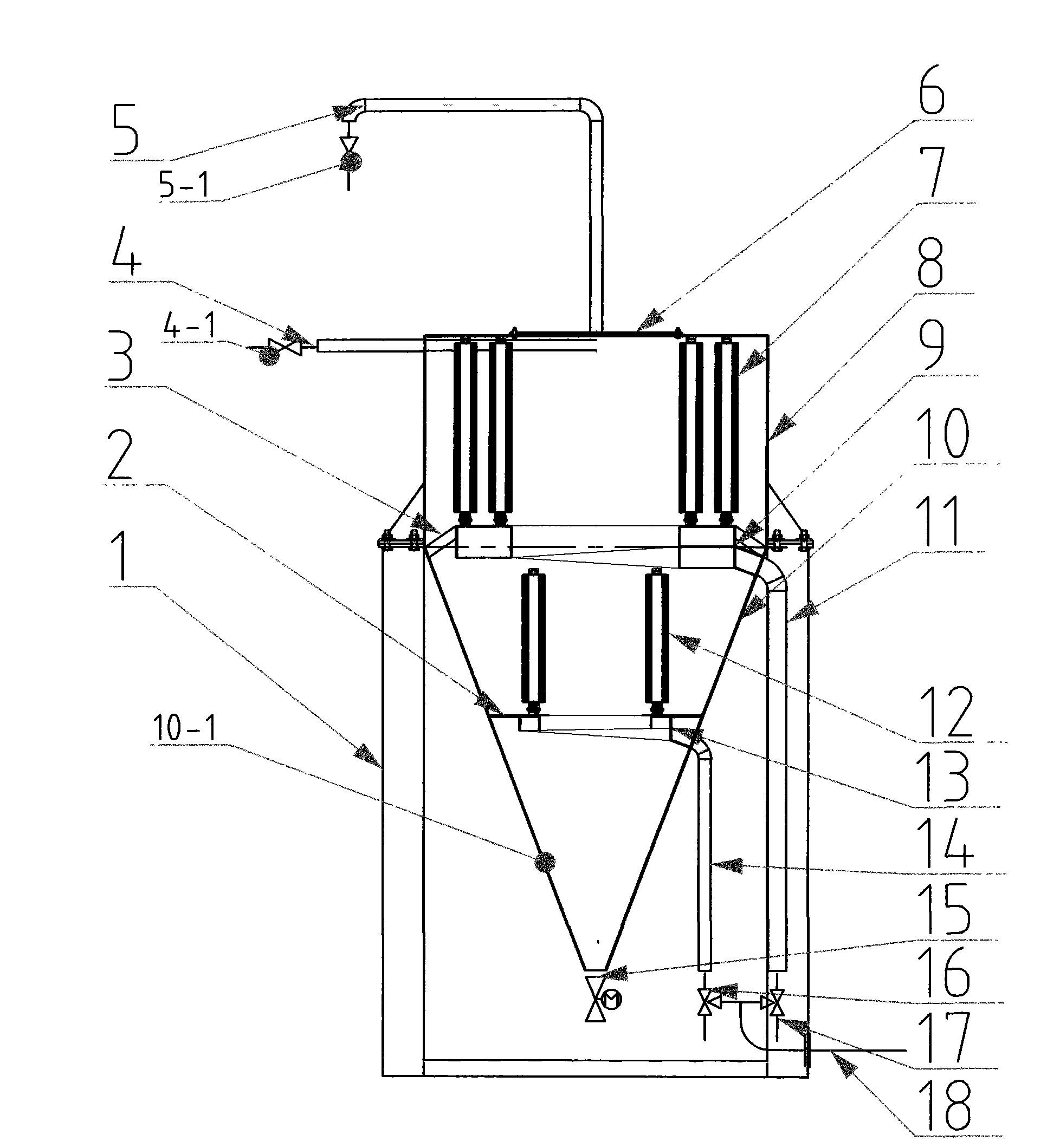
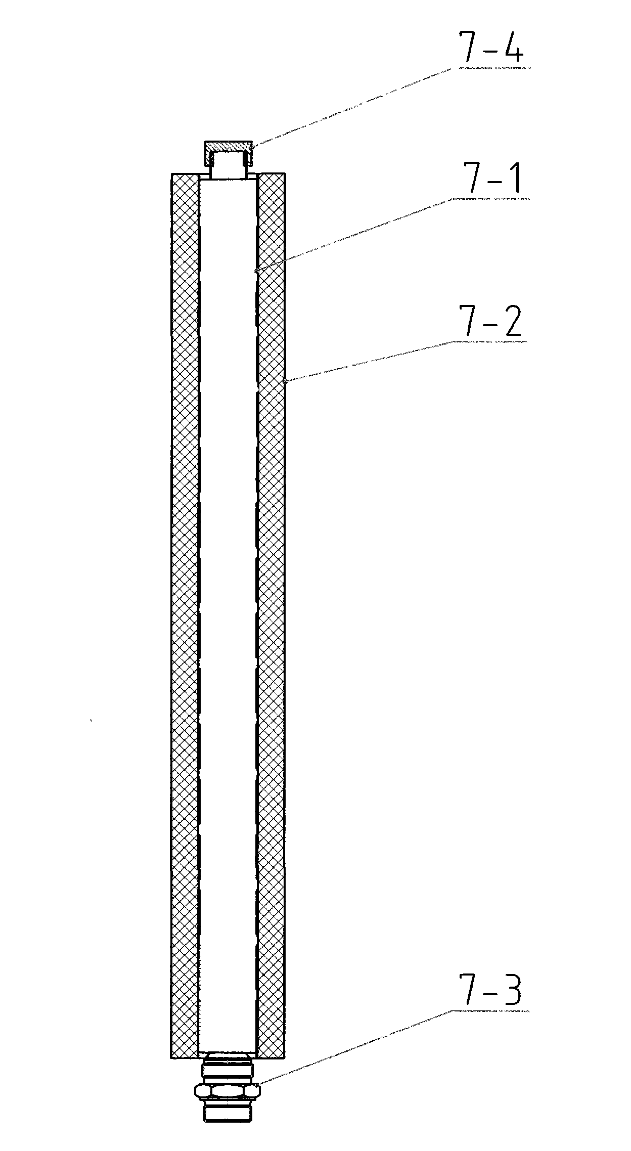
[0015] The bottom of the separator straight cylinder (8) is welded with a separator cone (10), which forms the tower body of the cyclone separator. The middle waist of the separator cone (10) is welded with a porous partition (2), and the lower part of the cone It is the mud collecting bucket (10-1), the tower body is installed on the bracket (1), the water inlet pipe (4) is installed in the tangential direction on the upper part of the tower body, and the water inlet water volume regulating valve (4- 1), the overflow pipe (5) is installed on the top of the tower body, the overflow valve (5-1) is installed on the overflow pipe (5), the inspection cover (6) is installed on the top of the tower body with connecting bolts, and the mud collecting bucket A mud discharge valve (15) is installed at the bottom of (10-1), and a number of adsorption, filtration and separation pipes (7) are arranged in a ring and vertically installed on the drainage collector (9), and the drainage is conn...


PUM

PropertyMeasurementUnit
diameteraaaaaaaaaa
diameteraaaaaaaaaa

Abstract

The invention discloses a rotational flow absorption filter concentration and separation technique and a device thereof, which belong to the technical field of solid-liquid separation. A solid-contained liquid with low concentration enters a separator tangentially; the kinetic energy of the entered water leads the solid-contained liquid in the separator to rotate around the center and scour the surface of an absorption filter separation tube arranged in the separator so as to lead the surface to be not easy to form an over-thick filter cake layer; the clear liquid in the solid-contained liquid is drained out by a Millipore super absorbent material coated by the absorption filter separation tube; the flowing directions of the solid-contained liquid and the separation liquid are crossed to form cross-flow separation; and then the solid-contained liquid can be concentrated and the substrate sludge with high concentration deposited at the tapered bottom of the separator is discharged by a sludge valve. The use of the technique and the device leads to better filter effect of the clear liquid. The solid-content of the discharged sludge is improved by 1 to 3 times than that of the sludge of a traditional concentrated tank; and the treatment amount can achieve 100-300m / m.d. The device simultaneously replaces a sedimentation tank, the concentrated tank and a filter, leads the separation process to be in a closed state, can have no electromechanical power during the separation process, can greatly reduce the dosage of flocculating agent (coagulating agent) and can even reduce the dosage of flocculating agent (coagulating agent) to zero.

Description

Technical field [0001] The technical field of the present invention is to provide a solid-liquid separation process and equipment, in particular to the technical route and device for concentrating and solid-liquid separation of solid-containing liquids with similar solid-liquid specific gravity by adopting the process method of cyclone adsorption filtration . Background technique [0002] At present, the known cyclone solid-liquid separation technology utilizes the rotating solid-containing liquid to undergo different centrifugal forces due to its different solid-liquid specific gravity, so that the components with large specific gravity gather toward the edge of the vortex, and the components with small specific gravity flow toward the edge of the vortex. The center of the vortex gathers to achieve the purpose of solid-liquid concentration and separation; it has the advantages of simple structure, small footprint, low manufacturing and operating costs, and continuous and re...

Claims


Application Information

Patent Timeline
Patent Type & Authority Applications(China)
IPC IPC(8): B01D36/04
Inventor 熊四达
Owner 熊四达
Learn More