Nanowire structures comprising carbon
A nanostructure and nanowire technology, applied in structural parts, nanotechnology, nanotechnology, etc., can solve the problem that nanowires are not disclosed
- Summary
- Abstract
- Description
- Claims
- Application Information
AI Technical Summary
Problems solved by technology
Method used
Image
Examples
preparation example Construction
[0192] In another embodiment, such as Figure 23 As shown in the flowchart 2300 of the present invention, the preparation method of the membrane electrode assembly of the present invention further includes: before disposing the first composition 2404 of the catalyst metal-associated nanowire (for example, a nanowire solution containing an ionomer) in step 2304 , in step 2310, a masking layer (eg, a metal film or foil) is disposed adjacent to the gas diffusion layer 2402 to cover at least the edges of the gas diffusion layer. mask layer in Figure 24 Not shown in , but suitably, the masking layer is prepared so that it covers the edges of the gas diffusion layer 2402 but leaves an open, unmasked portion in the center of the gas diffusion layer 2402 . Such as Figure 24 As shown, arranging a first composition containing catalyst metal-associated nanowires (e.g., a nanowire solution containing an ionomer) produces an assembly in which the center of the gas diffusion layer is co...
Embodiment 1
[0215] Embodiment 1: Preparation of nanowire structure
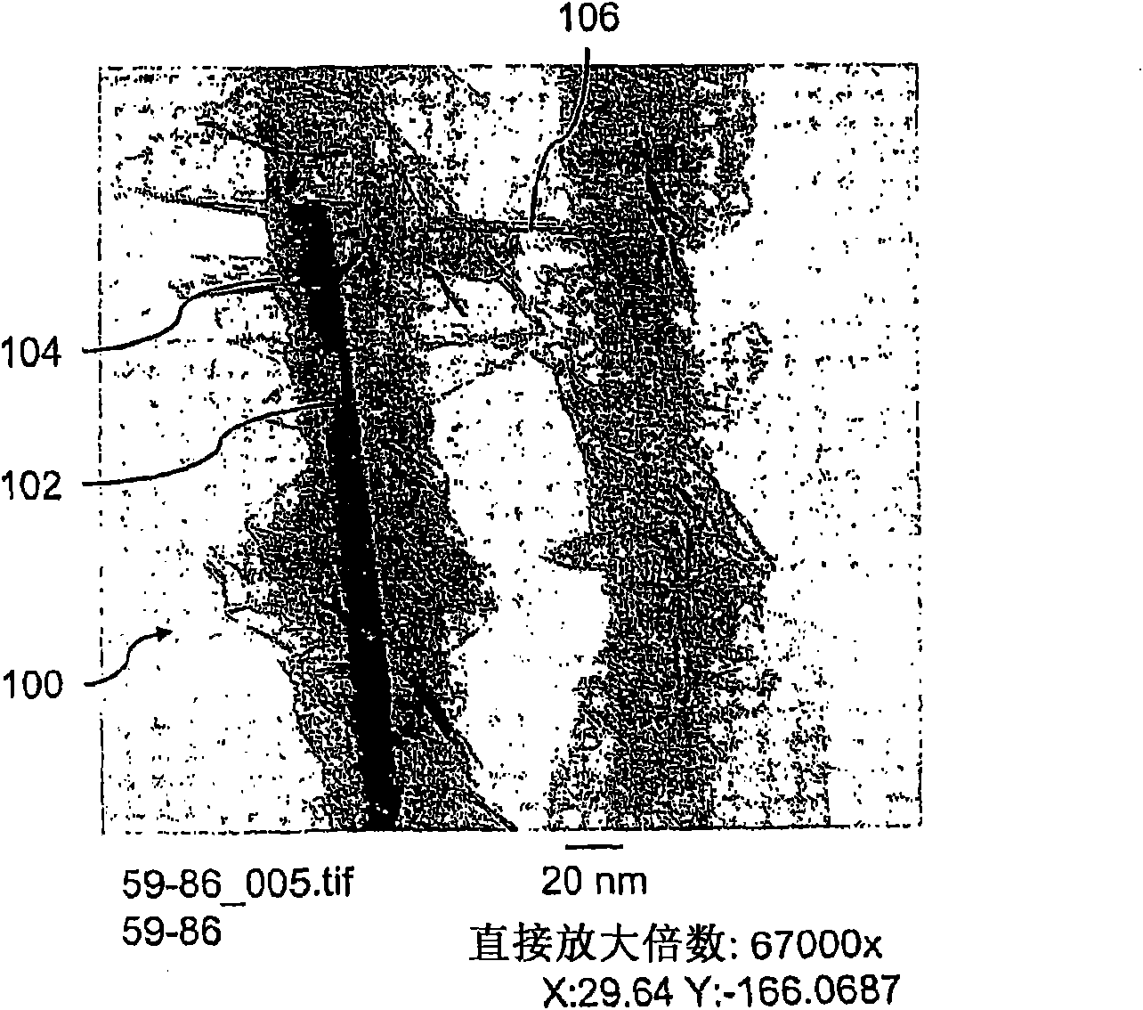
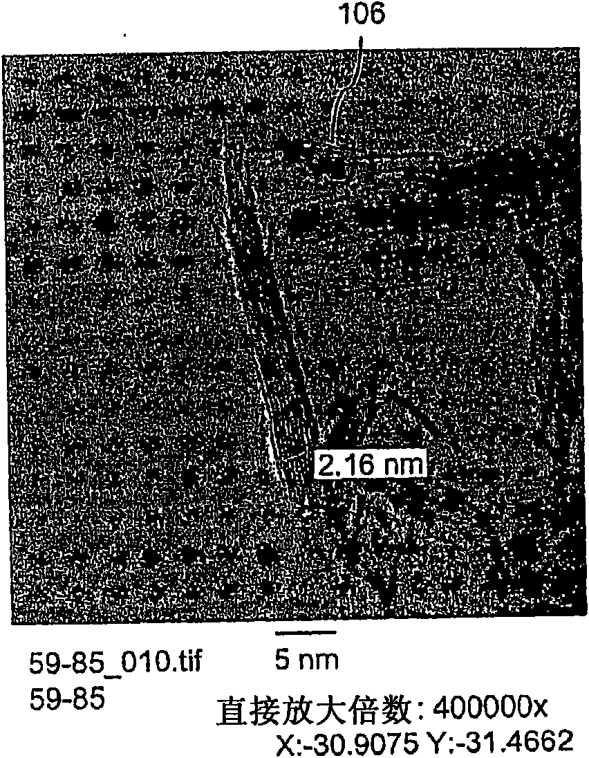
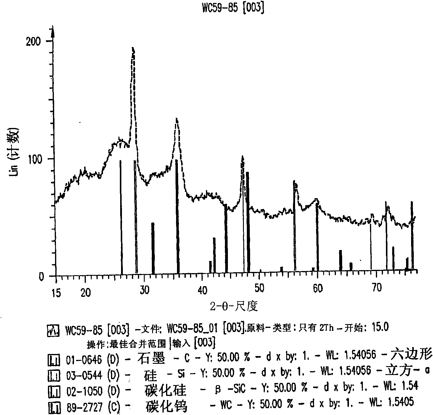
[0216] will be coated with WO 3 The silicon nanowires were heated at 650°C for 30 minutes, and then heated at 1250°C for 6 minutes in the presence of a flowing gas mixture containing Ar (430cc / min), H 2 (130cc / min) and CH in Ar 4 (228cc / min). After fabrication for cooling, an interconnected nanowire network 300 comprising interconnected nanowire structures 100 is formed. The nanowire structure 100 includes a Si nanowire core 102 , a carbon-based layer 104 (SiC / WC interface carbide layer) and a carbon-based structure 106 (graphene nanographite sheet) connecting the nanowire structure 100 .
Embodiment 2
[0217] Example 2: Deposition of nanoparticles on nanowires
[0218] Approximately 10 mg of Si nanowires were dispersed in ethanol by sonication to form a nanowire suspension. By vacuum filtering the nanowire suspension on a polyvinylidene fluoride (PVDF) membrane and vacuum drying, then adding 2cc of 0.1% polylysine solution to the filter funnel to adsorb polylysine on On the surface of the nanowires, a network of interconnected nanowires is produced. After 5 minutes, all liquid in the funnel was removed by vacuum, and the nanowire network was separated from the PVDF membrane. After drying in an oven at 100° C. for 15 minutes, the nanowire network was immersed in 10 cc of Au colloid solution (10 nm colloid) and soaked for 20 minutes to adsorb Au nanoparticles on the surface of the nanowires. Finally, the nanowire network was removed from the Au colloid solution, rinsed with isopropanol (IPA), and dried at 100° C. to obtain a nanowire network coated with gold nanoparticles. ...
PUM
| Property | Measurement | Unit |
|---|---|---|
| thickness | aaaaa | aaaaa |
| diameter | aaaaa | aaaaa |
| diameter | aaaaa | aaaaa |
Abstract
Description
Claims
Application Information
 - R&D
- Intellectual Property
- Life Sciences
- Materials
- Tech Scout
- Unparalleled Data Quality
- Higher Quality Content
- 60% Fewer Hallucinations
Browse by: Latest US Patents, China's latest patents, Technical Efficacy Thesaurus, Application Domain, Technology Topic, Popular Technical Reports.
© 2025 PatSnap. All rights reserved.Legal|Privacy policy|Modern Slavery Act Transparency Statement|Sitemap|About US| Contact US: help@patsnap.com


