Novel fluorescent lamp

A fluorescent lamp, a new type of technology, applied in the field of fluorescent lamps, can solve the problems of waste, easy burning of filaments, large power consumption, etc., and achieve the effect of stable brightness

Inactive Publication Date: 2010-12-08
余锐佳
View PDF0 Cites 0 Cited by
  • Summary
  • Abstract
  • Description
  • Claims
  • Application Information

AI Technical Summary

Problems solved by technology

[0004] The above-mentioned fluorescent lamps or energy-saving lamps must have a filament between two electrodes of different polarities. The fluorescent powder or saturated inert gas in the lamp tube is excited to light up by lighting the filament. The filament is easy to be blown. If the filament is broken, the entire lamp can no longer be used, which will cause trouble in frequent replacement of the lamp and cause waste
In addition, its power consumption is also relatively large

Method used


Image

  • Novel fluorescent lamp
  • Novel fluorescent lamp

Examples


Embodiment Construction

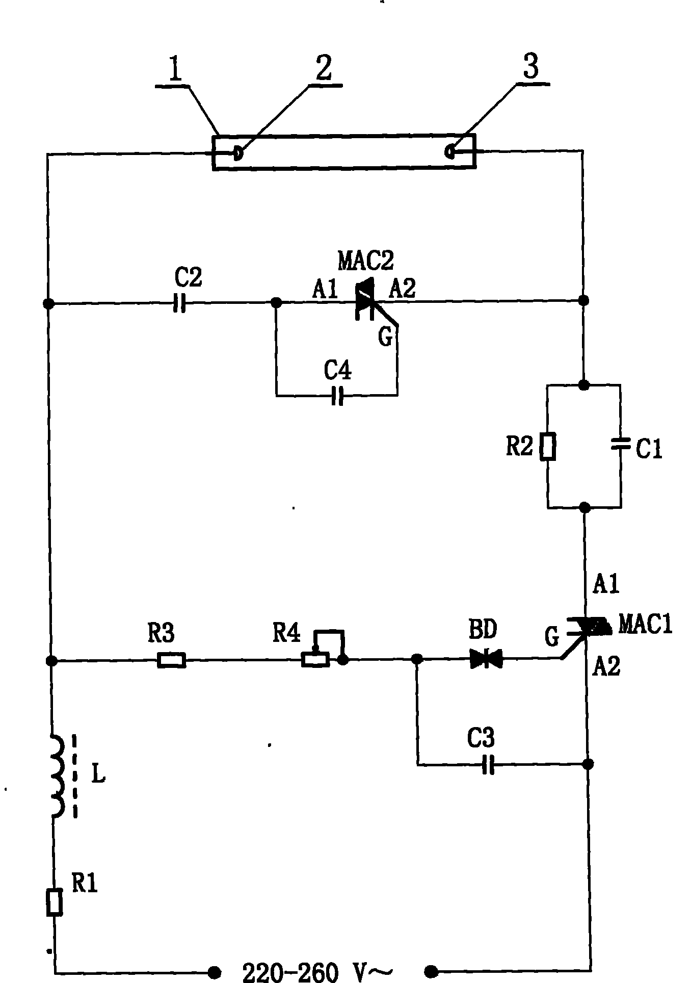
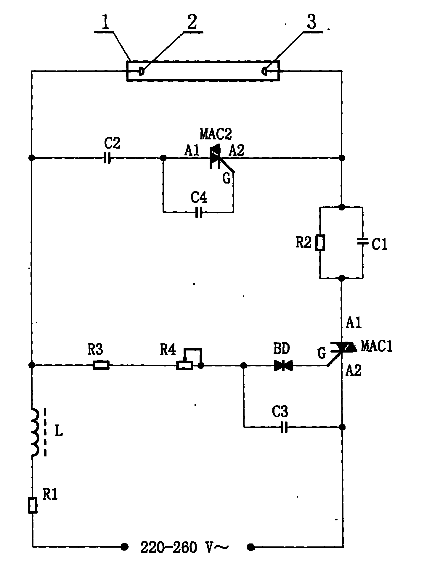
[0012] Attached below figure 1 Further illustrate the implementation of the present invention:

[0013] figure 1 It shows that the left end of the lamp tube 1 filled with fluorescent powder or saturated inert gas (this is the prior art part) is provided with an electrode 2, and the right end is provided with an electrode 3, and both the electrode 2 and the electrode 3 are in the shape of the lamp tube 1. Hemispherical.

[0014] After the resistor R1 is connected in series with the inductance transformer L, the remaining end of the inductance transformer L is electrically connected to the electrode 2 at the left end of the lamp tube 1, and the remaining end of the resistor R1 is electrically connected to the first phase of the AC power supply. After the resistance R2 and the capacitor C1 are connected in parallel, one end is electrically connected to the electrode 3 at the right end of the lamp tube 1, and the other end is electrically connected to the A1 pole of the bidire...


PUM


Abstract

The invention relates to a novel fluorescent lamp which comprises a lighting tube, electrodes, an inductance, a resistance and a capacitor, wherein, the left end and the right ends of the lighting tube are respectively provided with an electrode which are of a semicircle spherical shape in the lighting tube; the fluorescent lamp also comprises a trigger diode and bidirectional thyristors; in a circuit, one bidirectional thyristor is adopted to generate pulse voltage which is pressurized by a resistance-capacity coupling circuit to trigger the other bidirectional controlled silicon, thus arousing fluorescent powder or saturated inert gases in the lighting tube. As the fluorescent lamp is provided with a filament loop in the lighting tube, the problem of burning out filament does not exist,and part of electrical energy can not be consumed since the filament emits heat. In addition, the bidirectional thyristors are arranged, so that high voltage of the capacitance can be prevented from discharging towards the lighting tube suddenly after the lighting tube normally shines, and the lighting tube does not generate twinkle, thus the luminance brightness is stable.

Description

technical field [0001] The invention relates to the technical field of fluorescent lamps, in particular to a fluorescent lamp without a filament circuit. Background technique [0002] Conventional fluorescent lamps are filled with fluorescent powder or saturated gas in the lamp tube, and two sets of electrodes are arranged at both ends of the light, each set has two electrodes, and a filament is connected between the same set of electrodes; The filament is used to excite the fluorescent powder or saturated gas in the lamp tube to light up. On the circuit, the fluorescent lamp uses a ballast and a starter. [0003] The current energy-saving lamps are also filled with fluorescent powder or saturated gas in the lamp tube, and two sets of electrodes are arranged at both ends of the light, each set has two electrodes, and the same set of electrodes is connected by a filament; Light the filament to excite phosphor or saturated gas to light up. It's just that there is no ballast ...

Claims


Application Information

Patent Timeline
Patent Type & Authority Patents(China)
IPC IPC(8): F21S2/00F21V23/00H05B41/295F21Y103/00F21K9/238F21Y115/10
Inventor 余锐佳
Owner 余锐佳
Why Eureka
Try Eureka