A Method of Real-time Image Display in the Process of Ultrasonic Imaging Logging Data Acquisition

A technology for logging data and ultrasonic imaging, applied in the direction of digital output to display equipment, buildings, etc., can solve the problems of slow drawing speed, long time reading or generating images, and delay of probe pipe, etc., to improve drawing speed and real-time Displayed effect

Active Publication Date: 2022-05-20
BEIJING RES INST OF URANIUM GEOLOGY
View PDF0 Cites 0 Cited by
  • Summary
  • Abstract
  • Description
  • Claims
  • Application Information

AI Technical Summary

Problems solved by technology

[0004] However, in the process of drawing two-dimensional images of ultrasonic imaging logging data, due to the large amount of data and the large size of the drawn images, the drawing speed is usually slow and the acquisition position of the probe lags behind.
At the same time, during the acquisition process, you need to use the scroll bar to look back at the drawn image, and it takes a long time to read or generate an image each time

Method used


Image

  • A Method of Real-time Image Display in the Process of Ultrasonic Imaging Logging Data Acquisition

Examples


Embodiment Construction

[0041] The present invention will be described in further detail below with reference to the accompanying drawings and embodiments.

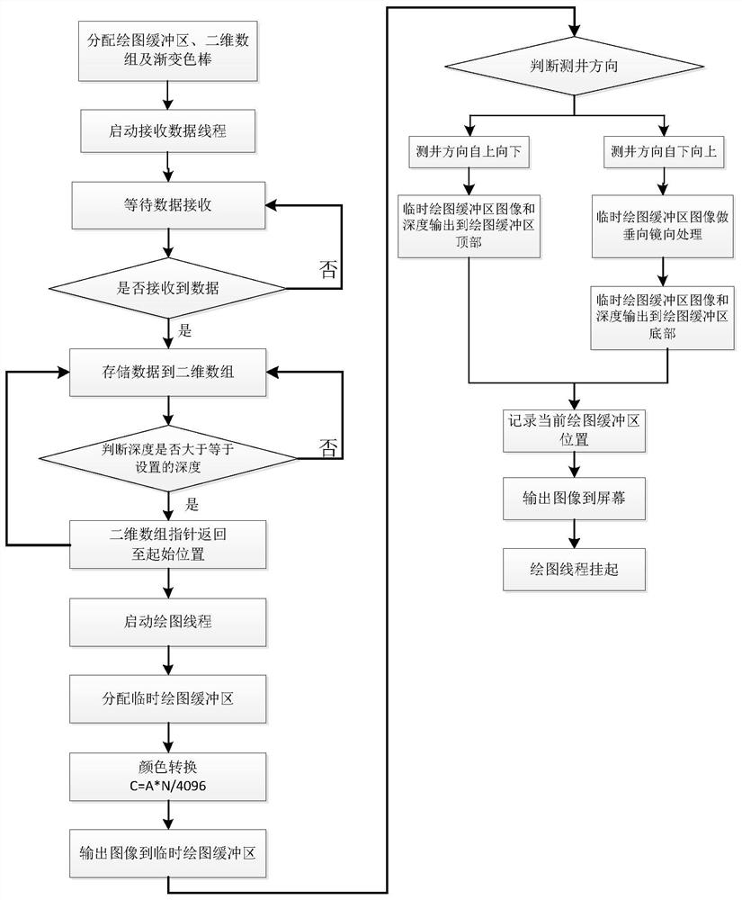
[0042] like figure 1 As shown, the method for real-time display of images in the process of acquiring logging data based on ultrasonic imaging provided by the present invention includes the following steps:

[0043] Step (1) Allocate a drawing buffer, define a two-dimensional array and define a gradient color bar, which specifically includes the following steps:

[0044] Step (1.1) Allocate the drawing buffer

[0045]Start the ground acquisition software in the computer. After the software is started, two drawing buffers, Ampbmp and Timebmp, are established in the memory to store the ultrasonic amplitude image and travel time difference image data respectively. The ultrasonic amplitude image data drawing buffer Ampbmp has a width of 45% of the screen resolution size and a height of 100000 pixels. The travel time difference image data drawing...


PUM


Abstract

The invention discloses a method for displaying images in real time during the acquisition process of ultrasonic imaging logging. Firstly, a drawing buffer and an array are allocated in the memory, and a color bar is established; when the computer starts the thread for receiving data, if no data It is in a waiting state, otherwise, store the received data into the array, and then judge whether the depth difference meets the set conditions, if so, start the drawing thread, otherwise continue to store data in the array; after the drawing thread starts, create a temporary drawing buffer , and convert each sampling point of the amplitude and travel time difference data in the array into the color in the color bar, and then output it to the temporary drawing buffer; then output the images in the temporary drawing buffer to different ways according to the logging direction In the drawing buffer created at the beginning, it is finally output to the screen, and the drawing thread is suspended, waiting for the next thread to start. The method can draw a two-dimensional image in real time and quickly, and the drawn image can be viewed through a scroll bar at any time during the acquisition process.

Description

technical field [0001] The invention belongs to the technical field of ultrasonic imaging logging and imaging, in particular to a method for displaying images on a screen in real time during acquisition based on an ultrasonic imaging logging tool. Background technique [0002] Ultrasonic imaging logging is to scan the borehole wall in an all-round 360-degree way by rotating the ultrasonic transducer in the downhole, collect the amplitude and travel time difference signals reflected by the ultrasonic wave through the borehole wall, and then upload it to the surface computer acquisition software. The processing technology presents two-dimensional images of amplitude and travel time difference in real time to reflect borehole wall information. [0003] The transducer transmits and receives ultrasonic signals several times for each rotation, and each signal is a horizontal sampling point. The more sampling points, the higher the lateral resolution. Each time the transducer rota...

Claims


Application Information

Patent Timeline
Patent Type & Authority Patents(China)
IPC IPC(8): G06F3/14E21B47/002
CPCG06F3/14E21B47/002
Inventor 乔宝强冯延强杨怀杰杨建涛
Owner BEIJING RES INST OF URANIUM GEOLOGY
Why Eureka
Try Eureka