
Electrolysis copper foil and circuit board

A technology of electrolytic copper foil and crystal distribution, applied in electrolytic process, electroforming, printed circuit parts, etc., can solve the problems of long manufacturing process, difficult to manufacture thin foil, unable to manufacture width, etc., and achieve the effect of improving flexibility

Active Publication Date: 2009-09-30
FURUKAWA ELECTRIC CO LTD
View PDF0 Cites 6 Cited by
  • Summary
  • Abstract
  • Description
  • Claims
  • Application Information

AI Technical Summary

Problems solved by technology

[0006] However, for rolled copper foil, the disadvantages are high processing cost due to long manufacturing process, it is impossible to manufacture wide copper foil, and it is difficult to manufacture thin foil, so electrolytic copper foil that can satisfy the above characteristics is required
[0007] However, in the existing manufacturing technology of electrodeposited copper foil, the manufacture of electrodeposited copper foil that satisfies all the above requirements while maintaining smoothness has not been proposed. Appearance of the above-mentioned flexible and bendable electrolytic copper foil

Method used


Image

  • Electrolysis copper foil and circuit board
  • Electrolysis copper foil and circuit board
  • Electrolysis copper foil and circuit board

Examples


Embodiment 1~5、 comparative example 1~3

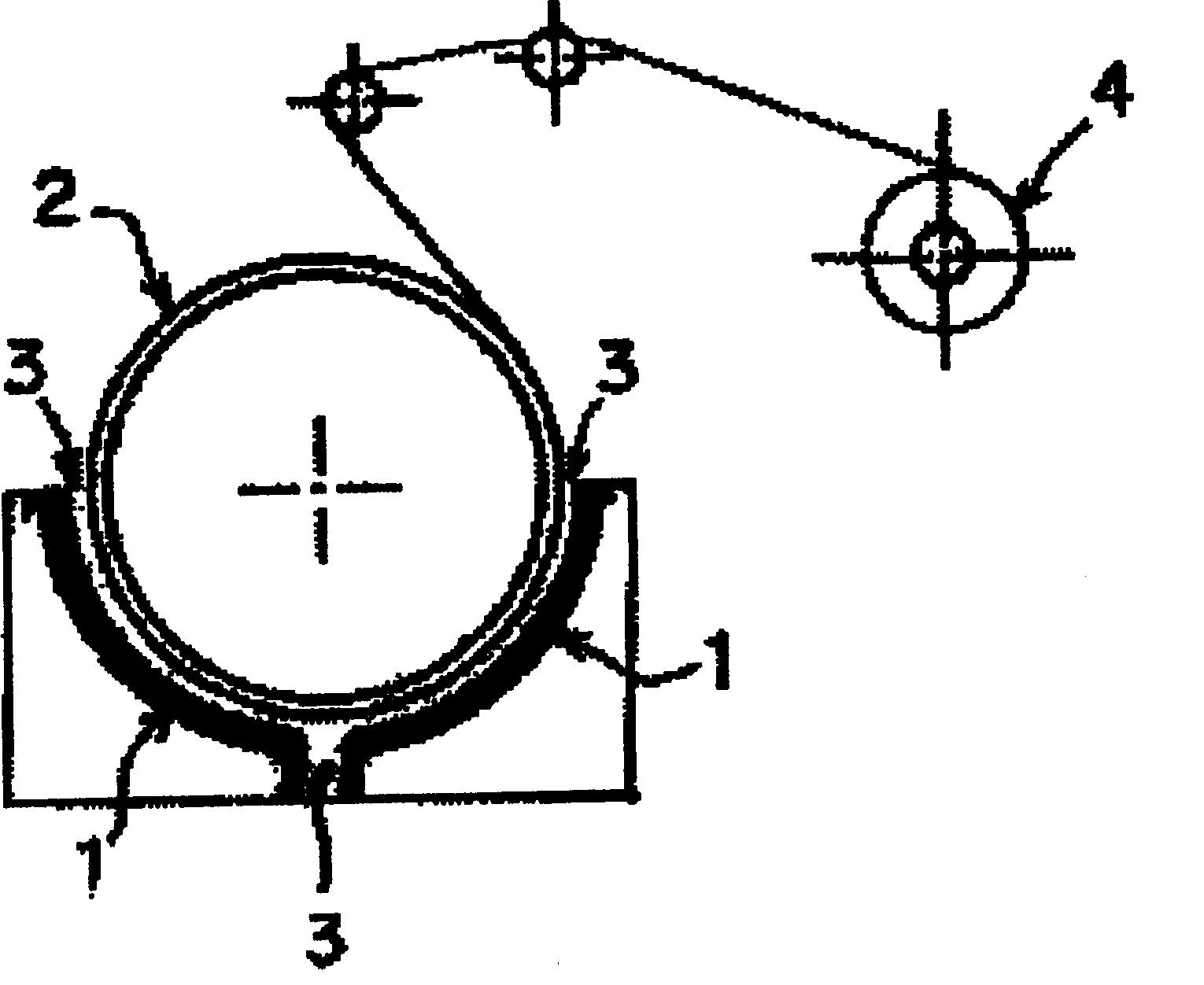
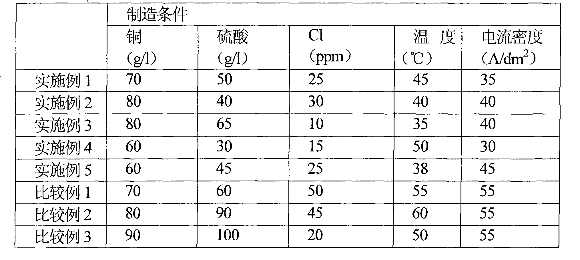
[0086] Table 1 shows the electrolytic solution composition. The copper sulfate electroplating solution (hereinafter referred to as the electrolyte) of the composition shown in Table 1 was cleaned by an activated carbon film, and the electrolytic foil was made by using a rotating drum foil making device to produce an untreated electrolytic copper foil with a thickness of 18 μm.

[0087] [Table 1]

[0088] Foil making conditions

[0089]

[0090] With regard to the produced untreated copper foil, the amount of impurities contained in the cross section of the copper foil and the surface roughness were measured. Next, the distribution (occupancy ratio) of crystal grains (with a maximum grain diameter of 4 μm or more) after heat treatment at a temperature setting consistent with the conditions of polyimide film thermocompression bonding was measured. The measurement (calculation) method is as follows.

[0091] 〔Impurities in the copper foil cross section〕

[0092] In the SIM...


PUM

PropertyMeasurementUnit
surface roughnessaaaaaaaaaa

Abstract

The invention provides an electrolytic copper foil with flexibility, bending behavior equal to or over roller copper foil, and provides a circuit board having flexibility and bending capability using the electrolytic copper foil. Especially, an electrolytic copper foil for circuit board with mechanical characteristic and flexibility improved in the process of adhering the electrolytic copper foil, applying and heating a polymide thin film, capable of electric equipment miniature adaptation. The electrolytic copper foil is produced by electrodialyzing on cathode, wherein crystalline grains having diameter over 4 mu m is over 80% in the electrolytic copper foil which is treated by a heat treatment represented by formula 1 with LMP over 8000. The formula 1 is LMP=(T+273)*(20+Log(t)), wherein T represents temperature (DEG C.), and t represents time (Hr).

Description

technical field [0001] The present invention relates to an electrolytic copper foil excellent in flexibility and flexibility. [0002] In addition, the present invention relates to printed wiring boards, multilayer printed wiring boards, and wiring substrates for chip on films (hereinafter, they are collectively referred to as wiring boards) using the electrolytic copper foil. Wiring boards for high-density, high-function applications. Background technique [0003] In the miniaturization of existing electrical equipment products, the bending angle (R) of the hinge portion of the mobile phone tends to become smaller and smaller, and the requirements for the bending characteristics of the wiring board are becoming stricter. [0004] In order to improve the bending characteristics, it is necessary to improve the thickness, surface smoothness, crystal grain size, mechanical characteristics, etc., which are important characteristics of the copper foil. In addition, for the mini...

Claims


Application Information

Patent Timeline
Patent Type & Authority Applications(China)
IPC IPC(8): C25D1/04C22F1/08H05K1/09
CPCB32B15/08C25D1/04C25D7/06
Inventor 铃木裕二斋藤贵广
Owner FURUKAWA ELECTRIC CO LTD
Learn More