
High energy electronic ignition system for high pressure gas well

A high-energy electronic and ignition system technology, which is applied in the petrochemical field, can solve the problems such as the water spraying out of the ignition, and achieve the effect of no safety hazard, easy to extinguish, and high discharge power.

Active Publication Date: 2009-09-23
BEIJING INSTITUTE OF TECHNOLOGYGY +2
View PDF0 Cites 5 Cited by
  • Summary
  • Abstract
  • Description
  • Claims
  • Application Information

AI Technical Summary

Problems solved by technology

[0005] In order to solve the above-mentioned technical problems, the present invention proposes a high-energy electronic ignition system for high-pressure natural gas wells that uses electronic ignition to ignite the combustible gas ejected from the blowout pipeline. Adopting the present invention, it can solve the problems of various current ignition methods. The ignition is easily extinguished by the sprayed water, high reliability, no safety hazard, accurate and efficient ignition performance, even in harsh environments, as long as the gas concentration reaches the lower limit of the combustion concentration, it can be successfully ignited

Method used


Image

  • High energy electronic ignition system for high pressure gas well
  • High energy electronic ignition system for high pressure gas well
  • High energy electronic ignition system for high pressure gas well

Examples


Embodiment 1

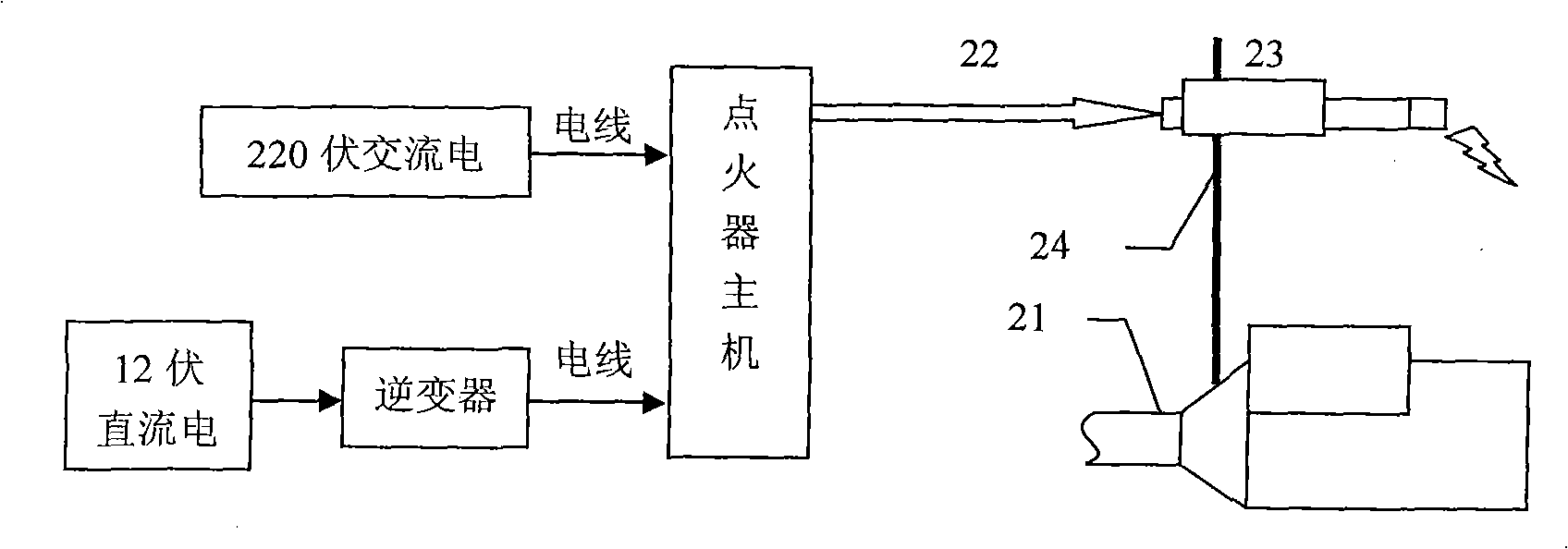
[0032] Refer to the attached figure 1 , the invention discloses a high-energy electronic ignition system for high-pressure natural gas wells, including an input power supply and a blowout device 21, the input power supply is connected to the main engine of the igniter, and the main engine of the igniter is connected to the ignition rod 23 through a fire-resistant cable 22, and the ignition rod 23 Be fixed on the top of the spraying device 21 through the ignition rod support 24, and the spraying device is a common spraying device in the prior art, and is made of parts such as spray barrels.

Embodiment 2

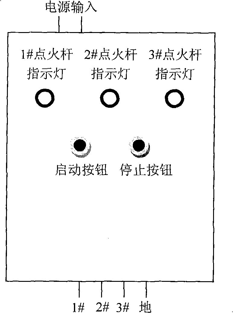
[0034] Refer to the attached image 3 Another embodiment of the present invention is that, on the basis of Example 1, the ignition host includes sequentially connected transformer circuit parts for converting the input power into 2000V high-voltage electricity, and a circuit for charging the input high-voltage electricity. An energy storage circuit portion and a discharge circuit portion that controls the release of stored electrical energy. The transformer circuit part includes an inverter for converting 12V direct current into 220V alternating current and a transformer for converting 220V alternating current into 2000V high voltage. The energy storage circuit part includes a diode, a capacitor, a resistor, a triac and an inductor, wherein the diode part is used to rectify the input 2000V high-voltage alternating current, and after passing through the current limiting resistor, the triac and the inductor control the circuit. Capacitor charging and discharging. The discharge...

Embodiment 3

[0036] Refer to the attached figure 1 , Another embodiment of the present invention is that on the basis of Example 1, the input power supply is two types, one is 220V AC, and the other is 12V DC.


PUM


Abstract

The invention discloses a high energy electronic ignition system for a high pressure gas well, which is suitable for igniting an open flow spout in the petrochemical field, especially the open flow field of the gas well (oil well). The high energy electronic ignition system for the high pressure gas well comprises an input power supply and an open flow device, wherein the input power supply is connected with a host machine of an igniter, the host machine of the igniter is connected with an ignition rod by a flame resistant cable, and the ignition rod is fixed above the open flow device by an ignition rod bracket. The high energy electronic ignition system for the high pressure gas well can solve the problem of various ignition modes that ignited fire is easy to be extinguished by spouted water; and the high energy electronic ignition system has the advantages of high reliability, no potential safety hazard and accurate and efficient ignition performance, and the operation of ignition can still be successfully carried out under the adverse environment in the premise that the gas concentration reaches the lower limit of inflammation concentration.

Description

technical field [0001] The invention relates to an ignition system suitable for directly igniting a blowout port in the petrochemical field, especially in the blowout field of natural gas wells (oil wells). Background technique [0002] Natural gas wells (oil wells) usually discharge a large amount of combustible gas and brine and other substances in the blowout pipeline during the production process or when a blowout occurs. These substances have a fast flow rate and contain flammable and explosive substances such as methane, hydrogen sulfide and sulfur dioxide. , toxic gas, so ignition as soon as possible is one of the most effective measures to reduce casualties. At present, there is no effective way to solve this problem in China. The 11.20 blowout accident in Dazhou occurred because a large amount of high-pressure combustible gas was not ignited at the first time, which made the blowout process out of control. [0003] At present, there are mainly three ignition method...

Claims


Application Information

Patent Timeline
IPC IPC(8): F02P3/02
Inventor 钱新明雷明黄平李昌卫孙文磊梁锋
Owner BEIJING INSTITUTE OF TECHNOLOGYGY
Learn More