Hydroelectric generating device

A technology for hydroelectric power generation devices and generator sets, which is applied in the directions of hydroelectric power generation, renewable energy power generation, engine components, etc., can solve problems such as difficulty in predicting and controlling electric power, not too small investment scale, pollution, etc.

Inactive Publication Date: 2013-08-14
沙同家
View PDF1 Cites 0 Cited by
  • Summary
  • Abstract
  • Description
  • Claims
  • Application Information

AI Technical Summary

Problems solved by technology

[0002] The current power generation devices, such as thermal power and nuclear power plants, need to consume a large amount of natural resources that are difficult to regenerate, and cause a lot of pollution in various aspects; and the current hydroelectric generating units, due to the limitations of their own structure, cannot be large Receive energy in a large area, so it is necessary to store water to create momentum, in order to use higher potential energy to convert into larger kinetic energy to drive the water turbine to generate electricity, so it is necessary to build dams and reservoirs. Therefore, the investment scale is generally relatively large. At the same time, It also brings ecological variables to a certain extent, or even forced immigration; and the current tidal power generation is actually similar to the existing hydropower generation, and it is also used to build reservoirs and store water for power generation, so its investment scale is not large. Not too little, and it also destroys the ecological landscape; in the existing wind and solar power generation, due to its low energy density, it is not easy to concentrate a large installed capacity, and because of their unpredictability ( Such as the weather, the size of the wind, etc.), so the power it produces is also relatively difficult to predict and control

Method used


Image

  • Hydroelectric generating device
  • Hydroelectric generating device
  • Hydroelectric generating device

Examples


Embodiment Construction

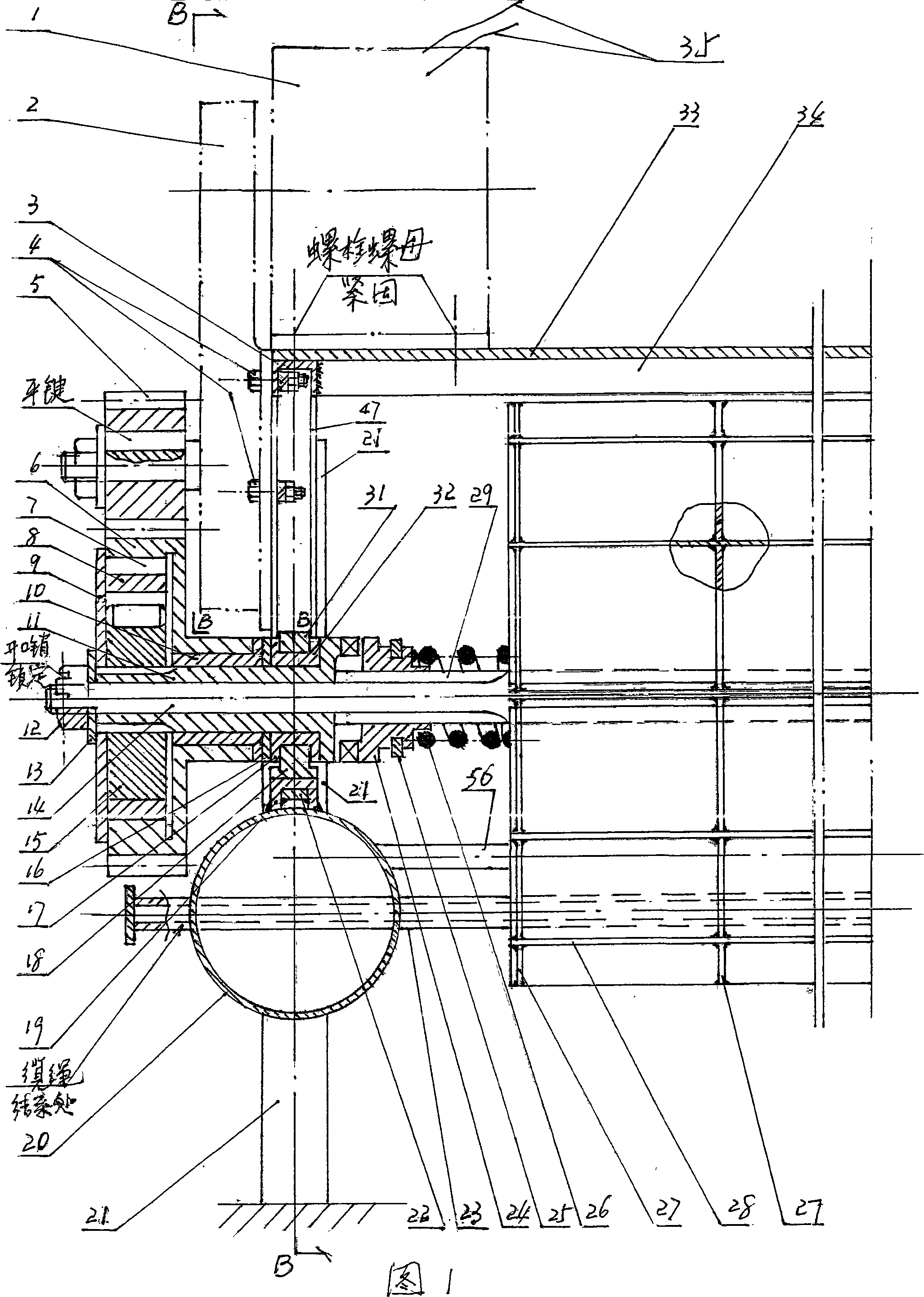
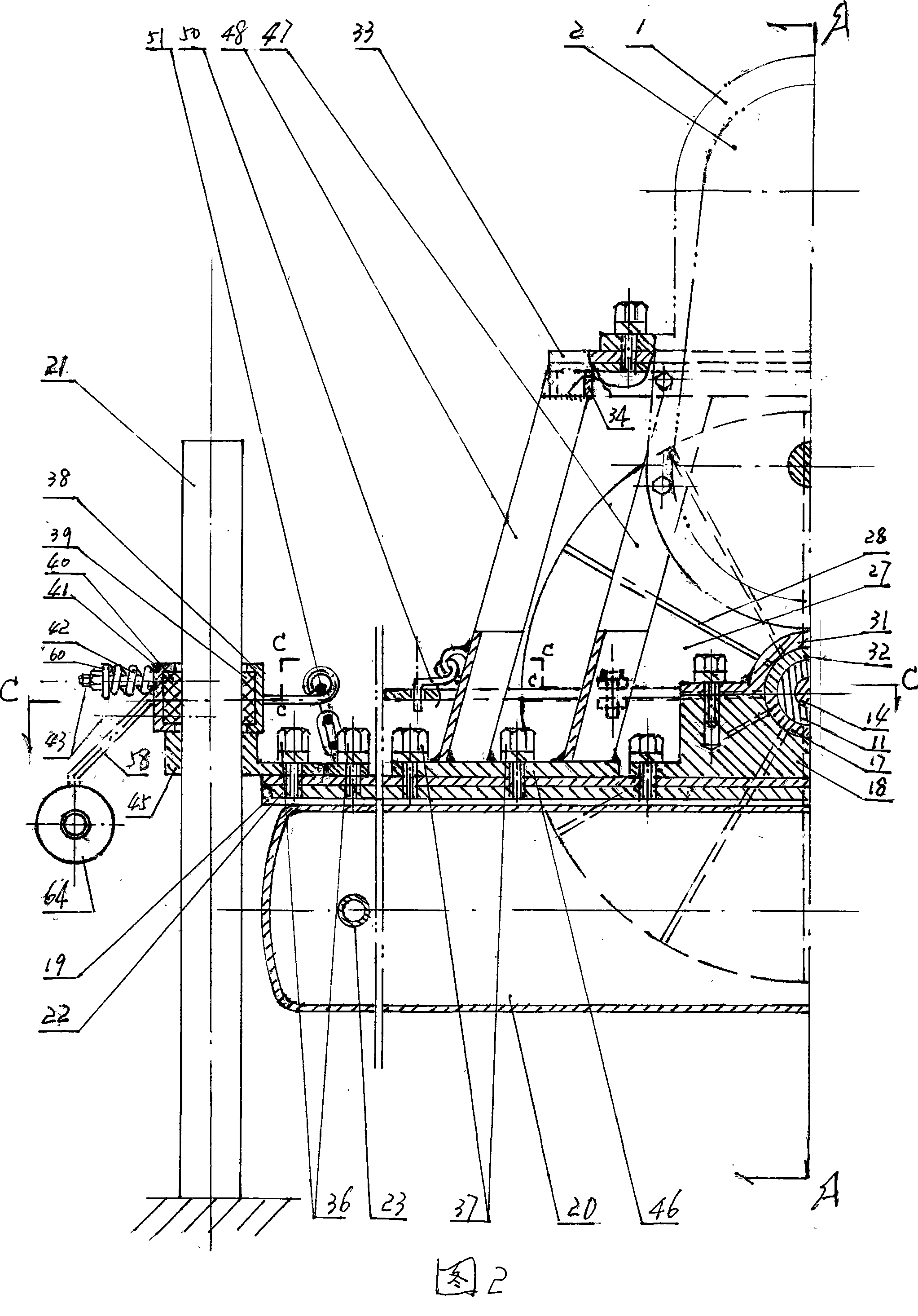
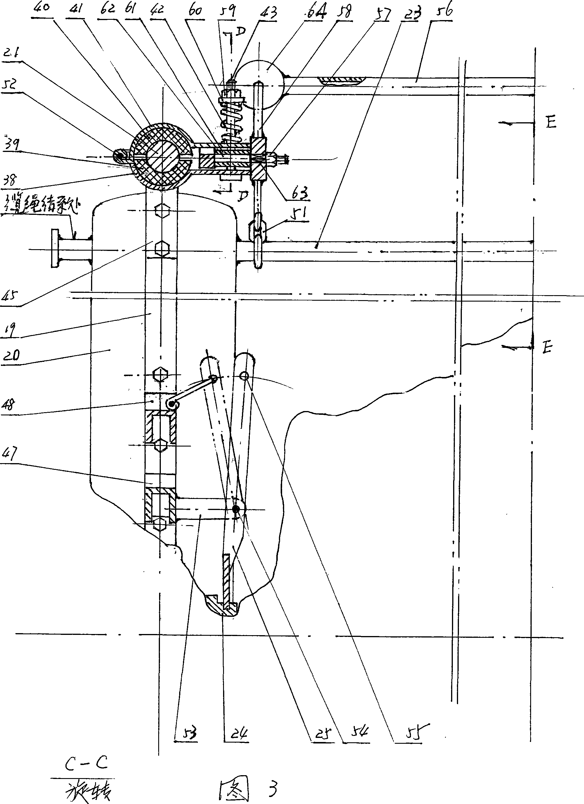
[0030] Such as figure 1 , figure 2 , image 3 , Figure 4 Shown: there are four cylindrical columns 21 to stand up from the water in the form of a rectangular matrix. A cylindrical sleeve 45 with a long handle is placed on each of them. In the middle of the front and back two cylindrical columns 21 on the left and right sides, there is a closed cylindrical buoy 20 respectively, i.e. left (right) buoy 20 (below for any right piece symmetrical with the left piece, or with the front The symmetrical rear parts of the parts will use a label with the left part or the rear part respectively, but only the parts that do not appear in the accompanying drawings are placed in brackets, such as: (right) floating barrel). Above the left (right) floating bucket 20, an opening is welded downwards and longer than the channel-shaped steel beam 19 of the floating bucket 20 along the direction of its generatrix, that is, the left (right) longitudinal beam 19. On the bottom of the groove of ...


PUM


Abstract

The invention relates to a hydroelectric generating device utilizing micro pressure energy to generate electricity. The horizontal orientation is determined by four upright posts and sleeves, and a left floating drum and a right floating drum are used for adapting to the water level change. In water which directionally flows, a left electric generating set and a right electric generating set can simultaneously generate the electricity; or the left electric generating set and the right electric generating set also can simultaneously generate the electricity by using an electrode automatic switching device in the water with relatively lower flow direction conversion frequency; or a left overrunning coupler and a right overrunning coupler with opposite torque transmission directions are usedfor adapting to the conversion of the water flow direction at any time. A creep type contracting brake can guarantee the effective utilization to water energy of the hydroelectric generating device, and the specific position of the hydroelectric generating device also can be determined and adjusted through the buoyancy of the left floating drum and the right floating drum and four cables.

Description

(1) Technical field [0001] A hydroelectric power generation device, especially a power generation device that utilizes only a small amount of hydraulic pressure head—that is, a flowing water body with a relatively low pressure difference (hereinafter referred to as: micro pressure head water body) to generate electricity. The tide of sea water or the flowing water in rivers or rivers is used to generate electricity. (2) Background technology [0002] The current power generation devices, such as thermal power and nuclear power plants, need to consume a large amount of natural resources that are difficult to regenerate, and cause a lot of pollution in various aspects; and the current hydroelectric generating units, due to the limitations of their own structure, cannot be large Receive energy in a large area, so it is necessary to store water to create momentum, in order to use higher potential energy to convert into larger kinetic energy to drive the water turbine to generate...

Claims


Application Information

Patent Timeline
Patent Type & Authority Patents(China)
IPC IPC(8): F03B3/12F03B13/00
CPCY02E10/223Y02E10/20
Inventor 沙同家
Owner 沙同家
Why Eureka
Try Eureka