
Method for improving LED external quantum efficiency

A technology of light-emitting diodes and external quantum efficiency, which is applied to electrical components, circuits, semiconductor devices, etc., can solve problems such as inability to export chips and large differences in refractive index, and achieve the effects of reducing operating voltage, improving leakage, and improving light output efficiency

Active Publication Date: 2009-09-02
HC SEMITEK SUZHOU
View PDF0 Cites 51 Cited by
  • Summary
  • Abstract
  • Description
  • Claims
  • Application Information

AI Technical Summary

Problems solved by technology

At present, the light extraction efficiency of the chip is the main factor limiting the external quantum efficiency of the device. The main reason is that the refractive index difference between the epitaxial layer material, the substrate material and the air is large, resulting in the light generated in the active region having different refractive index. Total reflection occurs at the material interface and cannot be exported to the chip

Method used

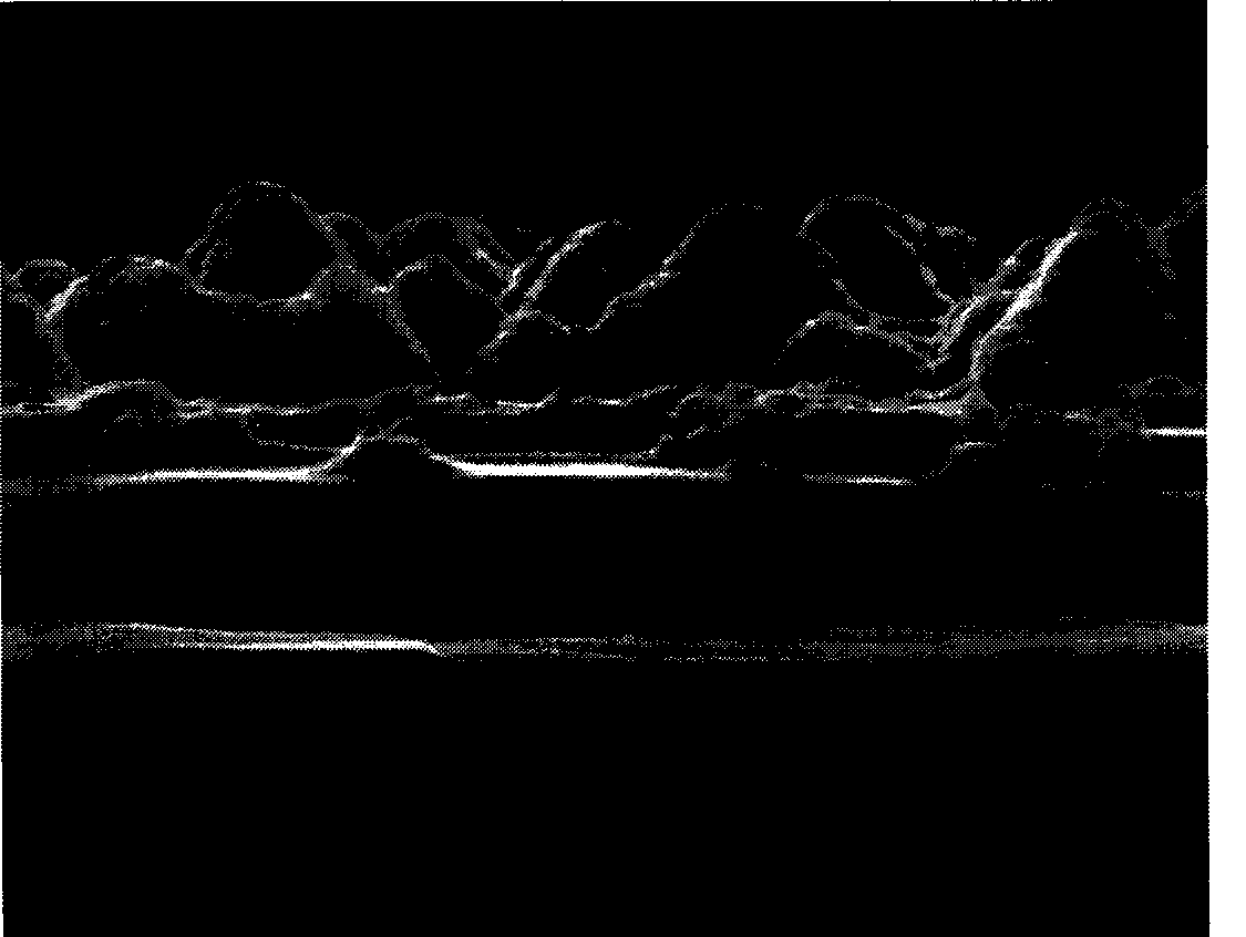

Image

  • Method for improving LED external quantum efficiency
  • Method for improving LED external quantum efficiency
  • Method for improving LED external quantum efficiency

Examples


Embodiment 1

[0031] Such as Figure 4 Shown:

[0032] (1) Substrate 1: first anneal the sapphire substrate at a temperature of 1120°C in a pure hydrogen atmosphere, and then perform nitriding treatment;

[0033] (2) Low-temperature buffer layer 2: Lower the temperature to 585°C to grow a 20nm-thick low-temperature GaN nucleation layer. During this growth process, the growth pressure is 420 Torr, and the V / III molar ratio is 900;

[0034] (3) High-temperature buffer layer 3: After the growth of the low-temperature buffer layer 2 is completed, stop feeding TMGa, raise the substrate temperature by 1120° C., and perform annealing treatment on the low-temperature buffer layer 2 in situ. The annealing time is 8 minutes; after annealing , adjust the temperature to 1120°C, and epitaxially grow high-temperature undoped GaN with a thickness of 1.2 μm under a lower V / III molar ratio. During this growth process, the growth pressure is 200 Torr, and the V / III molar ratio is 1500 ;

[0035] (4) N-type...

Embodiment 2

[0049] In Example 2, the growth methods of the epitaxial layers 1, 2, 3, 4, 5, 6, 7, 8, 10, and 11 are the same as those in Example 1. The difference lies in the growth method of the P-type layer 9: the doping molar ratio of Mg in this layer is reduced: Mg / Ga=1 / 16. An epitaxial wafer with a surface roughness smaller than that of Example 1 can be obtained.

[0050] After the chip manufacturing process and testing under the same conditions, the optical output power of a 11×11mil single small chip is 15.7mW, the working voltage is 3.15V, and it can be antistatic: the human body model is 5000V.

Embodiment 3

[0052] The difference between embodiment 3 and embodiment 1 lies in the growth thickness of the P-type layer 9: in embodiment 3, the growth thickness of the P-type layer 9 is 200 nm.

[0053] After the chip manufacturing process and testing under the same conditions, the optical output power of a 11×11mil single small chip is 18.7mW, the working voltage is 3.32V, and it can be antistatic: the human body model is 5000V.


PUM

PropertyMeasurementUnit
Thicknessaaaaaaaaaa

Abstract

The invention discloses a method for improving the LED external quantum efficiency. The growth mode of a P-shaped layer in an LED epitaxial wafer structure adopts the following novel coarsening method: improving the doping concentration of Mg in the P-shaped layer so as to reach the effect of coarsening the surface of the epitaxial wafer. The coarsened layer can be any layer or any multiple layersin the P-shaped composite layer, or a certain area in a certain layer. The method not only ensures a higher hole concentration, but also provides a coarsened surface. The LED surface coarsened layercan change the direction of light rays meeting a total reflection law, break down the total reflection of the light rays inside the LED, improve the light emission efficiency, and consequently improvethe external quantum efficiency.

Description

technical field [0001] The invention relates to a new method which can be applied to semiconductor light-emitting diodes, especially gallium nitride-based blue-green light-emitting diodes, and can effectively improve its external quantum efficiency. Background technique [0002] Semiconductor light-emitting diodes have the advantages of small size, high efficiency and long life, and are widely used in traffic indication, outdoor full-color display and other fields. In particular, the use of high-power light-emitting diodes (LEDs) may realize semiconductor solid-state lighting, which has caused a revolution in the history of human lighting, and has gradually become a research hotspot in the field of optoelectronics. However, the current industrialized LED luminous efficiency is only about 501m / W, and its efficiency is much lower than that of traditional light sources. The internal quantum efficiency of LED has reached more than 80%. In order to obtain high-brightness LED, th...

Claims


Application Information

Patent Timeline
IPC IPC(8): H01L33/00
Inventor 刘玉萍魏世祯孙飞
Owner HC SEMITEK SUZHOU
Learn More