
Plasma coal cracking reaction apparatus relating to flow screening component

A plasma and reaction device technology, which is applied in the field of plasma coal cracking reaction device, can solve the problems of easily damaged electrodes, low energy utilization efficiency, and the difficulty of increasing the mixing effect of coal powder and plasma jet, so as to achieve coal conversion and Improved heat conversion capacity, enhanced contact and mixing efficiency, and facilitated engineering scale-up design

Inactive Publication Date: 2009-08-19
TSINGHUA UNIV +1
View PDF0 Cites 14 Cited by
  • Summary
  • Abstract
  • Description
  • Claims
  • Application Information

AI Technical Summary

Problems solved by technology

Although the pre-device mixing occurs, to be precise, the reactants enter the arc zone, which is beneficial to the heating and mixing of raw materials, and can obtain high acetylene yields, but it is easy to damage the electrodes, and the device structure is relatively complicated.
Most of the test setups use the latter, but this increases the difficulty of achieving a good mixing effect between the pulverized coal and the plasma jet; this is mainly due to the high velocity of the plasma jet, while the incident velocity of the pulverized coal is much lower , the incident depth of pulverized coal in the high-speed plasma jet is limited, and this contradiction will become more prominent when the reaction device is enlarged
[0007] For the above-mentioned coal cracking reaction device that adopts the post-mixing operation mode of the plasma generator, since the pulverized coal is mainly concentrated in the periphery of the thermal plasma, the high-grade heat energy in the central area of ​​the thermal plasma has not been fully utilized, resulting in energy utilization less efficient

Method used


Image

  • Plasma coal cracking reaction apparatus relating to flow screening component
  • Plasma coal cracking reaction apparatus relating to flow screening component
  • Plasma coal cracking reaction apparatus relating to flow screening component

Examples


Embodiment 1

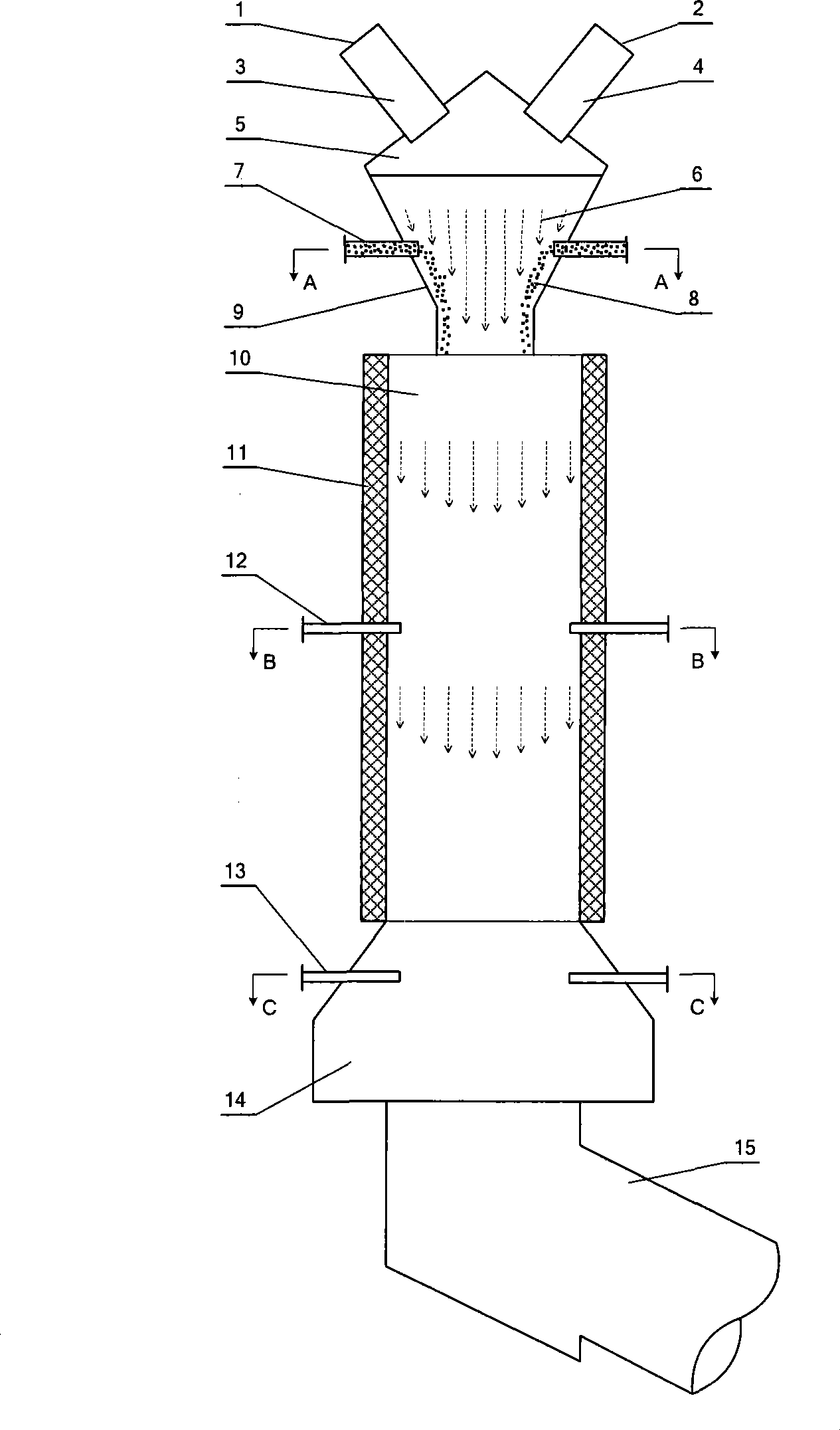
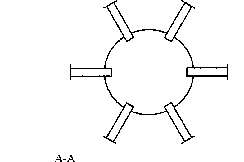
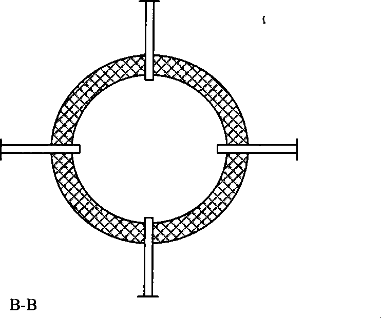
[0036] Figure 1a It is a schematic diagram of a plasma coal cracking reaction device without a shielding member, Figure 1b for Figure 1a A-A cross-sectional view of the mixing zone of the reaction device, Figure 1c for Figure 1a The B-B sectional view of the reaction zone of the middle reaction device, Figure 1d for Figure 1a C-C sectional view of the quenching zone of the medium reaction device. Such as Figure 1aAs shown, the plasma coal cracking reaction device without a shielding member includes: plasma torch anode working gas inlet 1, plasma torch cathode working gas inlet 2, plasma torch anode 3, plasma torch cathode 4 and plasma torch cathode and anode Convergence zone 5; mixing zone 9 and pulverized coal injection pipe 7; reaction zone 10, reaction zone wall surface 11 and reaction zone feed gas injection tube 12; quenching zone 14, quenching medium injection tube 13 and quenching zone outlet 15.

[0037] The plasma torch uses hydrogen as the working gas, the ...

Embodiment 2

[0043] This example is based on the improved plasma coal cracking reaction device in Example 1, and the reaction area shielding member is added.

[0044] Under the process conditions described in Example 1, the average temperature of the reaction zone is 1800-2500K, which is higher than the lowest temperature of 1400K for the formation and stable existence of acetylene. 12 The mixed gas of light aromatic fractions in coal tar and propane supplementary raw materials enters the reaction zone to participate in the cracking reaction, making full use of the heat in the reaction zone. The volume concentration of acetylene in the gas.

[0045] When no flow-shielding member is installed, the velocity of the reactant flow in the reaction zone 10 is 200-400m / s, and the velocity of the jet flow formed after the supplementary raw material mixture is sprayed through the raw material gas injection pipe 12 in the reaction zone is 40-80m / s, and its incident depth Not ideal enough, the contac...

Embodiment 3

[0050] This example is based on the improved plasma coal cracking reaction device in Example 2, and the quenching zone shielding member is added. Under the process conditions described in Example 2, the inlet temperature of the quenching zone is 1400-1800K, and water is used as the quenching medium to instantly cool the reactant flow to 600-800K. The cooling rate of 107-108K / s is the first necessary condition to ensure the acetylene yield in the process of plasma coal cracking to acetylene; the sufficient contact between the quenching medium and the reactant stream is the second necessary condition to ensure the acetylene yield.

[0051] When no blocking member is installed, the velocity of the reactant flow in the quenching zone 14 is 150-300m / s, and the velocity of the jet formed after the water is sprayed by eight quenching medium injection pipes 13 with an outer diameter of 5mm and an inner diameter of 4mm is 60-100m / s , The contact ratio with the reactant stream is 60-70%...


PUM


Abstract

The invention belongs to a plasma coal pyrolysis reactor involving cover flow components in the field of chemical equipment. The reactor comprises a plasma torch anode, a plasma torch cathode, a crossing area of the plasma torch anode and the plasma torch cathode, a working gas inlet of the plasma torch anode, a working gas inlet of the plasma torch cathode, a mixing area and a coal dust spraying tube, a reaction area, a reaction area wall surface, a reaction area feed gas injection pipe, a sharp quenching area, a sharp quenching medium injection pipe, a sharp quenching outlet and cover flow components arranged in the mixing area, the reaction area or the sharp quenching area. Cover flow components are arranged in the high temperature and high flow rate reactor, space distribution of fluid is changed, injection depth of injected material is increased, and contact and mixing efficiency between reactants is enhanced so as to realize the purpose of improving coal conversion and heat conversion capability of the reactor.

Description

technical field [0001] The invention belongs to the field of chemical equipment and relates to a plasma coal cracking reaction device related to a flow-shielding member. Background technique [0002] Acetylene is an important basic organic chemical raw material. The industrial methods for producing acetylene mainly include calcium carbide method, methane partial oxidation method and methane arc cracking method. Among them, the calcium carbide method acetylene process is mature and accounts for an absolute proportion in industrial production, but the pollution and energy consumption are relatively high. [0003] Plasma pyrolysis of coal to acetylene is a new and promising route for direct chemical conversion of coal. The related research began in the 1960s at the University of Sheffield in the UK: in the arc thermal plasma jet with high temperature, high enthalpy and high reactivity, Coal volatiles and even fixed carbon can be directly converted to acetylene. Since then, a ...

Claims


Application Information

Patent Timeline
IPC IPC(8): C07C11/24
Inventor 程易郭文康吴昌宁熊新阳周军金涌刘军
Owner TSINGHUA UNIV
Learn More