Process for producing track member, process for producing valve gear, and track member
A manufacturing method and component technology, which is applied in the manufacture of rail components, the manufacture of valve devices and the field of rail components, can solve the problems of rising manufacturing costs of rail components and increasing the number of heat treatment processes, and achieve the goal of ensuring rolling fatigue life and suppressing manufacturing costs The effect of rising and facilitating plastic processing
- Summary
- Abstract
- Description
- Claims
- Application Information
AI Technical Summary
Problems solved by technology
Method used
Image
Examples
Embodiment approach 1
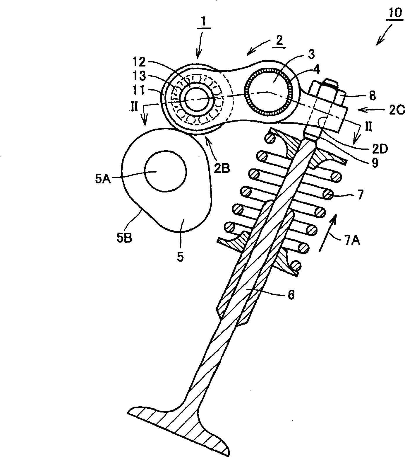
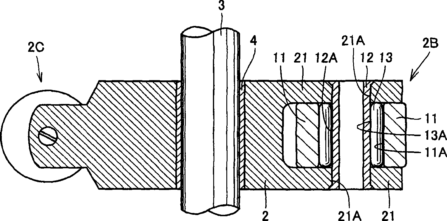
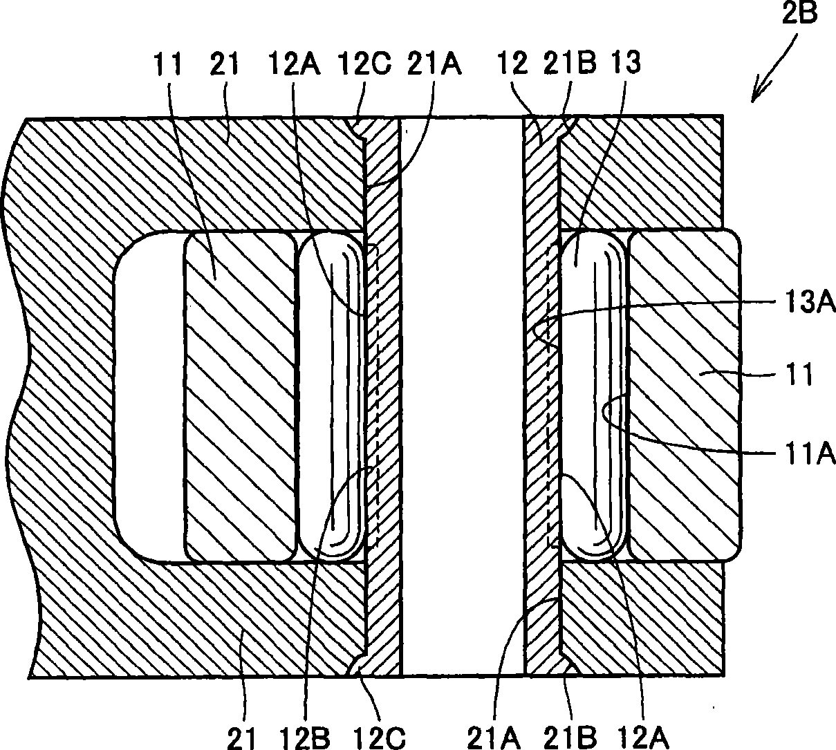
[0045] First refer to Figure 1 ~ Figure 3 A valve device equipped with a cam follower having a rail member according to Embodiment 1 will be described.
[0046] refer to figure 1 with figure 2 , the valve device 10 includes: a radial roller bearing of the total roller type, that is, a cam follower 1; a rocker arm 2 as a holding member for holding the cam follower 1 on one end 2B; a cam 5, the The cam 5 is arranged to be in contact with the outer peripheral surface of the roller 11 as the outer ring of the cam follower 1 on its outer peripheral surface 5B; The hole 2D is fixed on the rocker arm 2 by the lock nut 8; the valve 6, one end of the valve 6 is connected with one end of the adjusting screw 9, and is a valve for air supply or exhaust of the engine.
[0047] The cam follower 1 includes: an annular roller 11 as an outer ring; a hollow cylindrical shaft 12 passing through the roller 11 ; and a plurality of rollers 13 arranged between the roller 11 and the shaft 12 . ...
Embodiment approach 2
[0076] Refer below Figure 7 A valve device including a cam follower having a rail member and a method of manufacturing the same according to Embodiment 2 will be described.
[0077] refer to Figure 7 The valve device 10 of Embodiment 2 has basically the same structure as the valve device 10 of Embodiment 1 described above. The valve device 10 of the second embodiment differs from the valve device 10 of the first embodiment in that the pivot point of the rocker arm 2 is one end portion 2B of the rocker arm 2 .
[0078] That is, in the valve device 10 according to Embodiment 2, the pivot abutting portion 22 which abuts on the unillustrated pivot is formed on the one end portion 2B side of the rocker arm 2 . The rocker arm 2 can freely rotate with the pivot abutting portion 22 as a fulcrum.
[0079] When the cam 5 rotates around the camshaft 5A together with the camshaft 5A, the distance from the camshaft 5A to the contact portion between the cam 5 and the cam follower 1 per...
Embodiment approach 3
[0082] Refer below Figure 8 and Figure 9 A valve device equipped with a cam follower having a rail member and a method of manufacturing the same according to Embodiment 3 will be described.
[0083] refer to Figure 8 and Figure 9 The valve device 10 of the third embodiment has basically the same structure as the valve device 10 of the first embodiment described above. The difference between the valve device 10 of Embodiment 3 and the valve device 10 of Embodiment 1 is that the cam follower 1 is not directly mounted on the rocker arm 2 , but sandwiched between the rocker arm 2 and the cam follower 1 . A push rod 90 is provided, on which the cam follower 1 is mounted.
[0084] That is, a rod-shaped push rod 90 is connected to one end 2B of the rocker arm 2 through an adjustment screw 80 and a connecting member 81 , and the adjustment screw 80 is fixed on the rocker arm 2 by a lock nut 82 . The cam follower 1 is attached to the end portion of the push rod 90 serving as a...
PUM
| Property | Measurement | Unit |
|---|---|---|
| hardness | aaaaa | aaaaa |
| hardness | aaaaa | aaaaa |
Abstract
Description
Claims
Application Information
 - R&D
- Intellectual Property
- Life Sciences
- Materials
- Tech Scout
- Unparalleled Data Quality
- Higher Quality Content
- 60% Fewer Hallucinations
Browse by: Latest US Patents, China's latest patents, Technical Efficacy Thesaurus, Application Domain, Technology Topic, Popular Technical Reports.
© 2025 PatSnap. All rights reserved.Legal|Privacy policy|Modern Slavery Act Transparency Statement|Sitemap|About US| Contact US: help@patsnap.com


