Direct-connecting main spindle for multiple-spindle processor

A processing machine, direct connection technology, applied in the direction of metal processing machinery parts, metal processing equipment, manufacturing tools, etc., can solve the problems of increasing the production cost, increasing the production cost, affecting the processing quality, etc., to improve the processing quality and smooth the rotation. Action, cost-saving effect

Inactive Publication Date: 2009-07-01
SPINDER TECH
View PDF1 Cites 6 Cited by
  • Summary
  • Abstract
  • Description
  • Claims
  • Application Information

AI Technical Summary

Problems solved by technology

[0002] Multi-axis processing machines are equipped with multiple spindles with processing tools on a support frame that can be lifted and moved to drive each processing tool to perform processing operations synchronously. For example, multi-axis engraving and milling machines generally use built-in spindles. Main shaft, because the design of the built-in spindle is to configure the power source of the motor inside the main shaft, if the said built-in main shaft is applied to a single-axis processing machine, it can be convenient for the internal space due to the long design of the main shaft It is equipped with a motor power source, but the design length of the main shaft of the multi-axis processing machine is relatively short. In the case of limited internal space, the motor power source must be configured with higher precision, which is not only difficult to manufacture and assemble, but also significantly Increase the production cost; however, if the direct-coupled spindle with the motor mounted on the outside of the spindle can be applied to the multi-axis processing machine, it will be easier to manufacture and reduce the cost, and it can solve the problem of using the built-in spindle in the multi-axis processing machine The resulting lack; the current direct-joint spindle used in CNC processing machines, please refer to figure 1 As shown, it is the patent case of Taiwan Patent Application No. 88220034 "Structure Improvement of Direct-connected Spindle". A hollow tube type pressure cylinder 14 is arranged above the casing 13 outside the main shaft 10, and the pressure cylinder 14 is provided with a pressure cylinder seat 141 and a pressure cylinder cover 142 on the pressure ring 15 of the casing 13, and the A piston 143 is arranged above the moving part 12, and a hollow tube type pressure cylinder 14 can be used to connect with the main shaft 10 to provide the power source required for cutting and grasping the knife, and then the pressure cylinder 14 is equipped with a knife blowing pipeline And the hydraulic or pneumatic inlet and outlet pipelines are used to control the piston 143 to press against the stopper 12, so that the stopper 12 drives the ejector rod 11 to perform the operation of punching and grabbing the knife. The motor seat 17 on the 16 is used to set up the motor 18, and the rotating shaft 181 of the motor 18 is connected to the main shaft 10 with a coupling 19, so as to drive the main shaft 10 and the processing tool to rotate and perform machining operations; Type spindles have the following deficiencies in use:
[0003] 1. The main shaft 10 is provided with a hollow tube type pressure cylinder 14 composed of a cylinder base 141, a cylinder cover 142 and a piston 143 above the casing 13, which not only increases the volume of the direct-connected main shaft. Large, the assembly of the components of the cylinder 14 is also quite cumbersome and time-consuming, which increases the production cost
[0004] 2. The rotating shaft 181 of the motor 18 is connected to the main shaft 10 by a coupling 19, and there is no direct connection between the rotating shaft 181 and the main shaft 10, so that when the main shaft 10 rotates at high speed, the top end of the main shaft 10 tends to wobble, which further affects Processing quality

Method used


Image

  • Direct-connecting main spindle for multiple-spindle processor
  • Direct-connecting main spindle for multiple-spindle processor
  • Direct-connecting main spindle for multiple-spindle processor

Examples


Embodiment Construction

[0029] In order to enable your examiner to have a further understanding of the present invention, hereby cite a preferred embodiment and cooperate with the drawings, which are described in detail as follows:

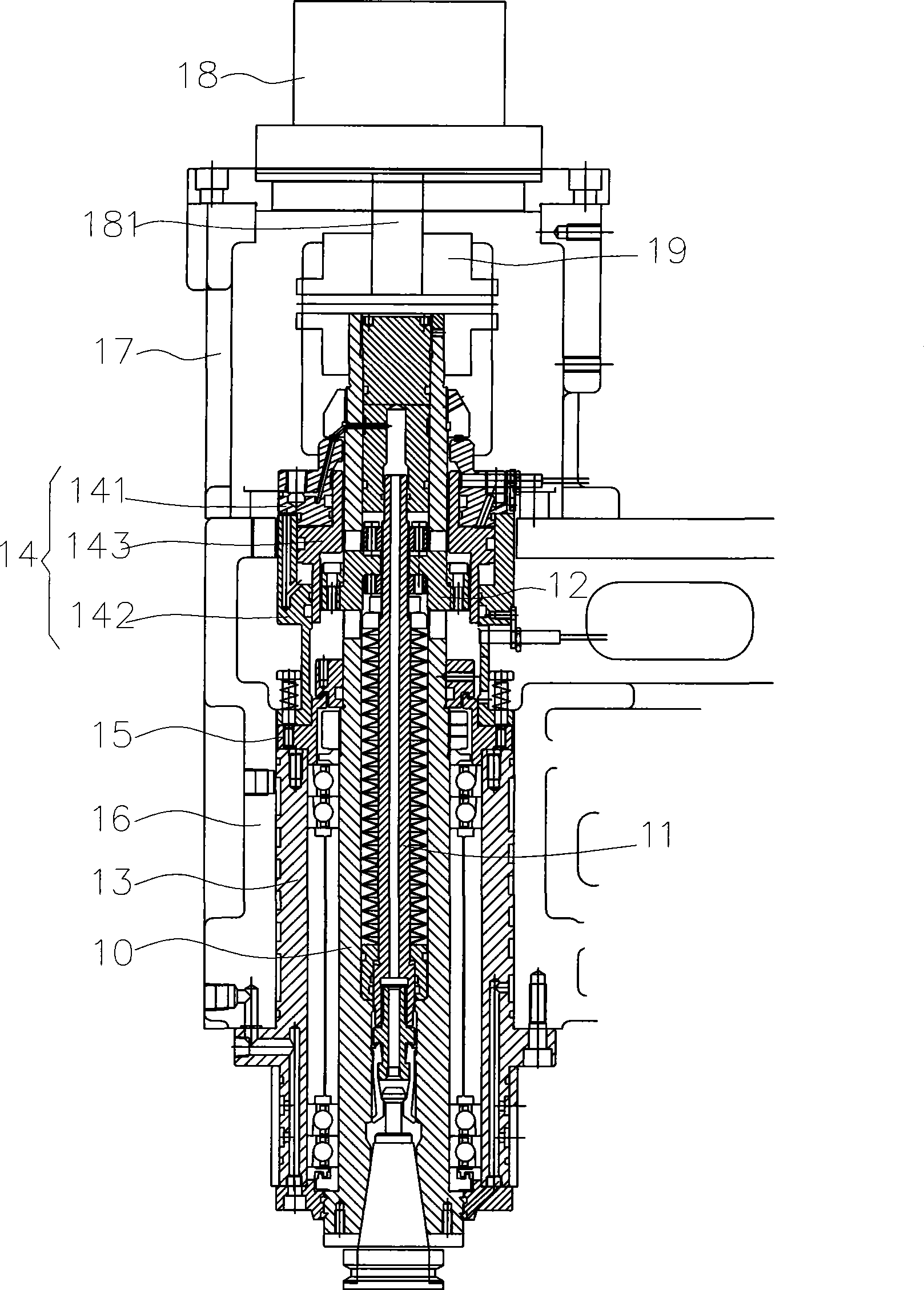
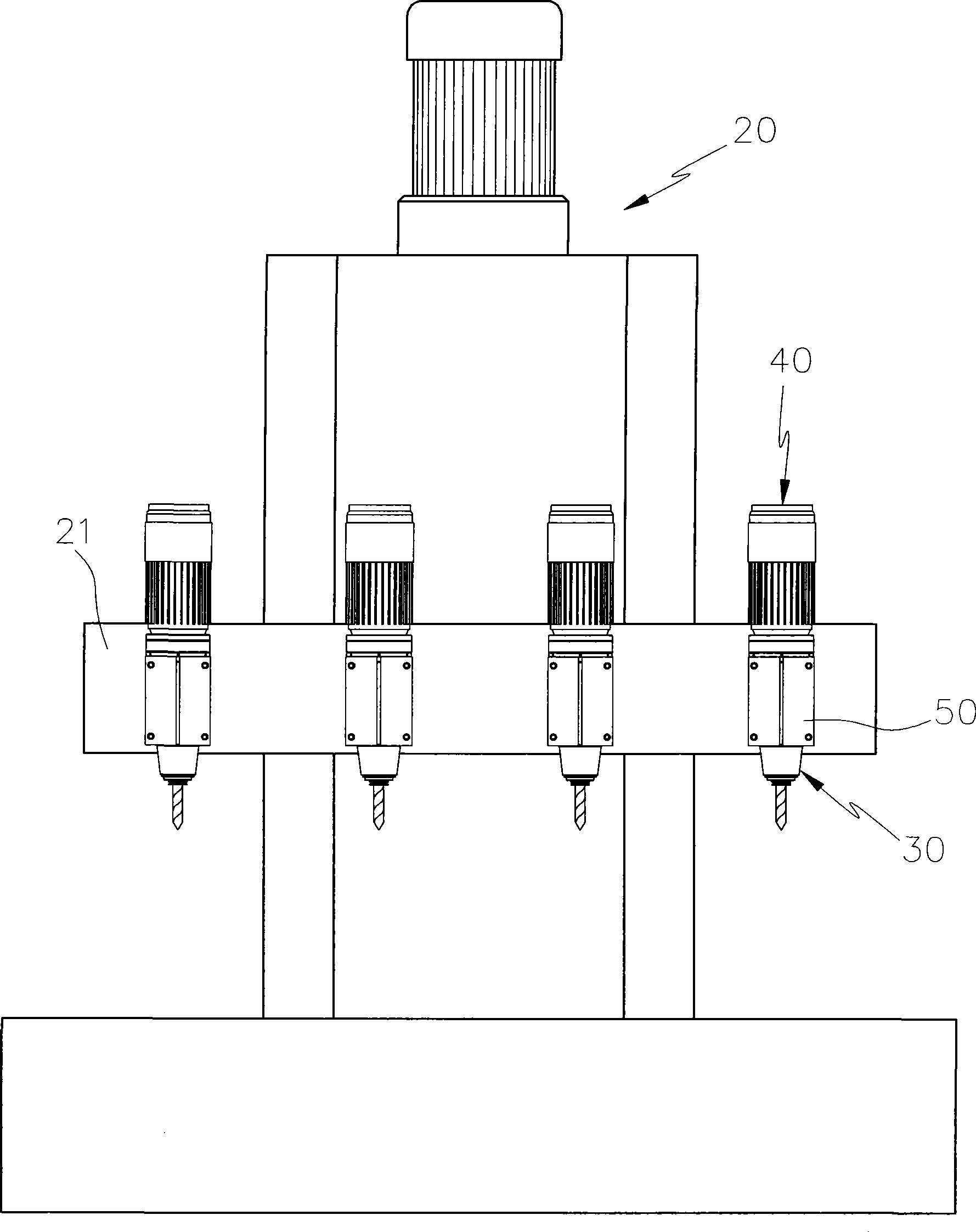
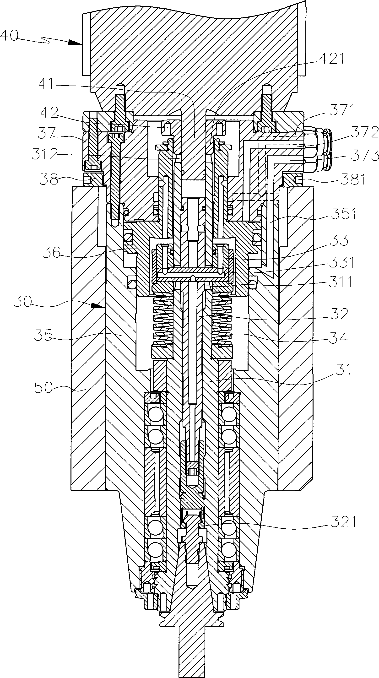
[0030] see figure 2 , image 3 , Figure 4 , Figure 5 As shown, the multi-axis processing machine 20 is provided with a support frame 21 that can be moved up and down, and a plurality of direct-connected spindles 30 are locked on the support frame 21, and each spindle 30 is provided with a long hole 311 The rotating shaft 31, the rotating shaft 31 is provided with a pull rod 32 with a jaw 321 inside to be used for hitting the knife and grabbing the knife, while a detent 33 is sleeved on the outside, and the detent 33 of the detent The bottom is the top spring 34, and the connecting rod 331 penetrates the long hole 311 of the rotating shaft 31 to connect the pull rod 32 to drive the pull rod 32 to move synchronously. Between the pull rods 32 there is a connected kni...


PUM


Abstract

The invention relates to a vertical junction main shaft used in a multishaft processing machine, wherein a plurality of the vertical junction main shafts are fixed on a lifting actuated load-bearing frame of the multishaft processing machine; the inside and outside of a rotating shaft of each main shaft are provided with coupled pull rods used to forge a knife and a brake piece; moreover, a sleeve outside each rotating shaft is taken as a pressure cylinder body, and the inside of the sleeve is provided with a piston used to press the brake piece for actuation; a motor seat fixed on the top of the sleeve is taken as a pressure cylinder cover, thereby forming an integral pressure cylinder outside the rotating shaft to drive the pull rod to carry out knife forging and grasping operations; the motor seat can be taken as a hydraulic adapter or an air-pressure adapter for assembling a tube body; in addition, a rotary shaft of the motor is provided with a shaft sleeve to connect the rotating shaft of each main shaft. Thus, the volume of vertical junction main shafts assembled on the multishaft processing machine can be reduced to save cost, and the rotating shaft of each main shaft can realize smooth rotation and actuation to improve processing quality; moreover, the motor seat has different use efficiencies to improve use convenience.

Description

technical field [0001] The invention relates to a direct-connected spindle of a multi-axis processing machine. Background technique [0002] Multi-axis processing machines are equipped with multiple spindles with processing tools on a support frame that can be lifted and moved to drive each processing tool to perform processing operations synchronously. For example, multi-axis engraving and milling machines generally use built-in spindles. Main shaft, because the design of the built-in spindle is to configure the power source of the motor inside the main shaft, if the said built-in main shaft is applied to a single-axis processing machine, it can be convenient for the internal space due to the long design of the main shaft It is equipped with a motor power source, but the design length of the main shaft of the multi-axis processing machine is relatively short. In the case of limited internal space, the motor power source must be configured with higher precision, which is not...

Claims


Application Information

Patent Timeline
Patent Type & Authority Applications(China)
IPC IPC(8): B23B19/02B23Q3/157B23Q3/12
Inventor 邱大文
Owner SPINDER TECH
Why Eureka
Try Eureka