
Device for cutting bone inside femoral head

A cutter and femoral head technology, applied in medical science, surgery, etc., can solve the problems of inability to effectively remove necrotic lesions, failure to prevent articular surface collapse, and limited amount of femoral head implanted bone, so as to facilitate postoperative rehabilitation , solve the waste of autogenous bone, and have a significant supporting effect

Inactive Publication Date: 2009-05-20
张纯朴
View PDF0 Cites 7 Cited by
  • Summary
  • Abstract
  • Description
  • Claims
  • Application Information

AI Technical Summary

Problems solved by technology

Osteotomy orthopedic surgery in invasive treatment is used to change the load-bearing area of ​​the femoral head. This kind of surgery has a better effect on cases with small lesions, but it often has a high potential morbidity after surgery; A better treatment method can restore the spherical surface of the femoral head and prevent further collapse, but this operation cannot prevent or delay the collapse of the articular surface; fenestration is to open a window at the junction of the articular surface of the femoral head and the head and neck, Autologous bone, bone cement or metal titanium mesh are implanted after necrotic lesions to maintain the shape of the articular surface of the femoral head and delay joint replacement; titanium rod implantation is to implant a 10mm mesh titanium rod under the articular cartilage, Supports the articular surface of the femoral head
The above-mentioned invasive treatment operations cannot effectively remove necrotic lesions, the amount of bone implanted in the femoral head is limited, and there is a problem of wasting autogenous bone

Method used


Image

  • Device for cutting bone inside femoral head

Examples


Embodiment Construction

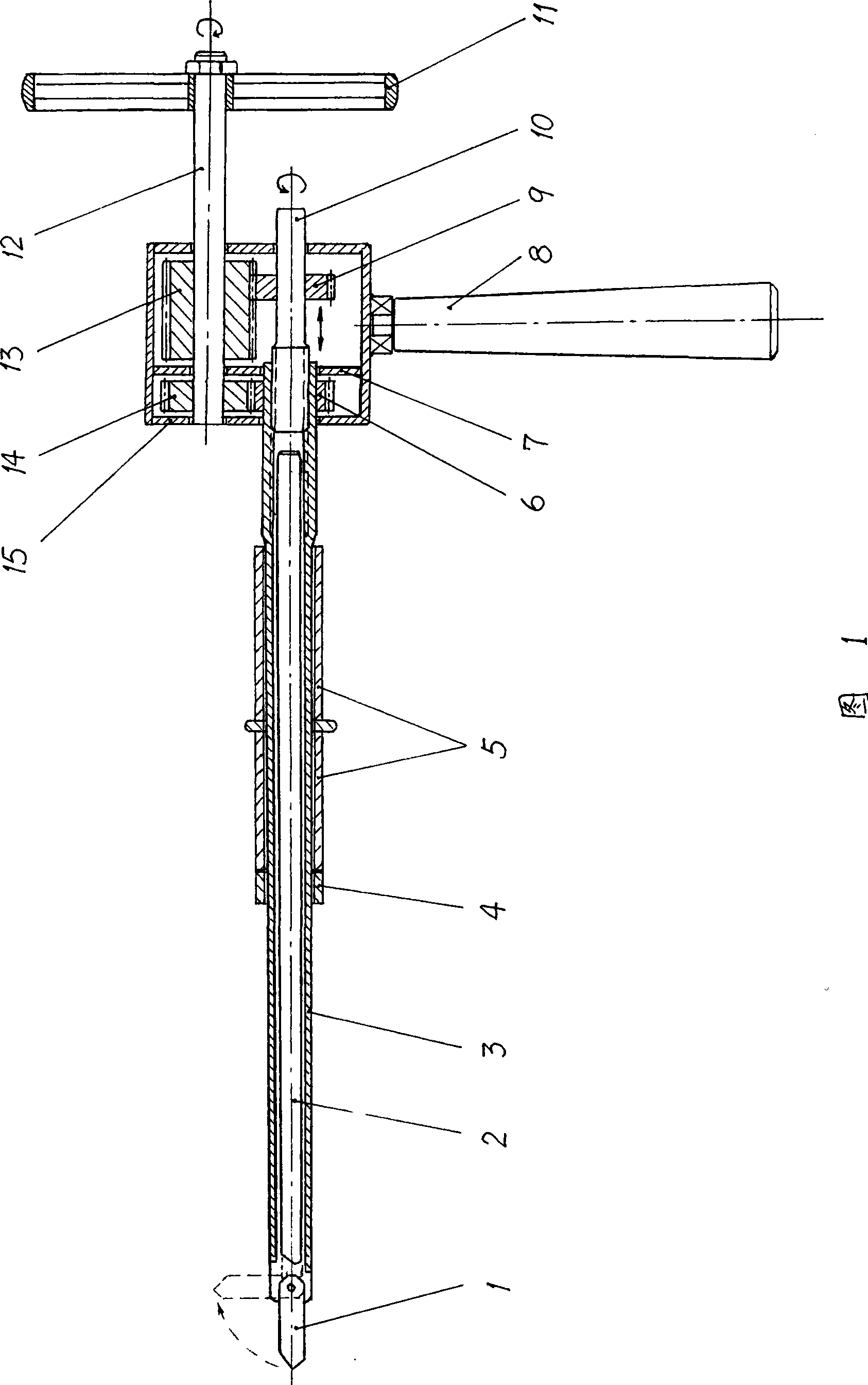
[0011] As shown in Figure 1, the bone cutter in the femoral head of the present invention includes several parts such as a rotary cannula 3, a rotary cutter 1, a differential gear transmission mechanism and a hand crank mechanism. The differential gear transmission mechanism includes a driving shaft 12 , a driven shaft 10 , two sets of meshing gears, a cubic housing 15 and an inner partition 7 . In FIG. 1 , the right end of the rotary intubation tube 3 , the driving shaft 12 and the driven shaft 10 are respectively passed through the housing 15 . Two driving gears are tapped on the driving shaft 12 on both sides of the inner partition 7, the driving gear on the left is a thin gear 14, and the driving gear on the right is a thick gear 13; the number of teeth on the thick gear is more than the number of teeth on the thin gear, so that Achieve a larger transmission ratio. The transmission gear 6 is sleeved on the inner extension end of the rotary intubation tube 3 (or made into ...


PUM


Abstract

The invention relates to a sclerotin-in-femoral head cutter for a bone surgery. The cutter comprises a rotary insertion pipe, a rotary cutting knife, a differential gear transmission mechanism and a hand-operated mechanism, wherein the hand-operated mechanism is connected with the exposed end of a driving shaft of the differential gear transmission mechanism; the front end of the rotary insertion pipe is connected with the rotary cutting knife, and the back end of the rotary insertion pipe is connected with a transmission gear of the differential gear transmission mechanism; one end of a driven shaft of the differential gear transmission mechanism is inserted in the back end of the rotary insertion pipe, and in threaded connection with the back end of the rotary insertion pipe; and an inner top rod is inserted in the rotary insertion pipe, and the front end of the inner top rod is provided with an eccentric pushing surface. Therefore, by utilizing the rotation and deflection, a dome type cutting space the cutting radius of which is far larger than the diameter of the rotary insertion pipe is formed on the front end of the rotary insertion pipe, and furthermore a novel and effective minimally invasive operation treating mode for femoral head necrosis is formed.

Description

technical field [0001] The invention relates to an orthopedic medical device, in particular to a femoral head bone cutter. Background technique [0002] Adult femoral head necrosis is a common orthopedic disease. The treatment methods of femoral head necrosis can be divided into non-invasive treatment and invasive treatment. Non-invasive treatment includes hyperbaric oxygen therapy, water wave therapy and oral medication; invasive treatment includes interventional therapy, heart medullary decompression, heart medullary decompression bone grafting, osteotomy orthopedic, vascularized bone grafting, titanium rod implantation, Hemiarticular replacement and total hip replacement. Osteotomy orthopedic surgery in invasive treatment is used to change the load-bearing area of ​​the femoral head. This kind of surgery has a better effect on cases with small lesions, but it often has a high potential morbidity after surgery; A better treatment method can restore the spherical surface...

Claims


Application Information

Patent Timeline
Patent Type & Authority Applications(China)
IPC IPC(8): A61B17/22A61B17/32
Inventor 张纯朴张奇
Owner 张纯朴
Learn More