
Cutting wire production method and cutting wire and tyre cutting device

A manufacturing method and technology of cutting device, which are applied in manufacturing tools, metal processing equipment, metal processing and other directions, can solve the problems such as difficulty in making bead saws too small, low lifespan of diamond wire saws, high noise and smoke pollution, etc. Small cutting force, fast cutting speed and wide range of applications

Active Publication Date: 2009-04-29
青岛厚泽锦业技术有限公司
View PDF9 Cites 16 Cited by
  • Summary
  • Abstract
  • Description
  • Claims
  • Application Information

AI Technical Summary

Problems solved by technology

However, hard and brittle materials represented by ceramics have high hardness and high brittleness, and are prone to collapse and damage during the cutting process, while high-toughness materials represented by tire rubber are prone to elastic deformation during the cutting process due to their high toughness. uneven
Therefore, these brittle or tough materials are difficult to cut by ordinary processing methods
[0003] At present, the known tire section cutting machines are divided into several forms, 1) toothless saw type, the cutting range is limited, the cutting quality is poor, and the noise and smoke pollution are large
2) Band saw type, poor cutting quality and low cutting efficiency
3) Water cutting type, the cutting quality is slightly better, but the cutting efficiency is lower
[0004] In addition, the diamond wire saw used in the existing cutting machine has disadvantages such as low service life, difficulty in making the diameter of the bead saw too small, and wide kerf.

Method used


Image

  • Cutting wire production method and cutting wire and tyre cutting device
  • Cutting wire production method and cutting wire and tyre cutting device
  • Cutting wire production method and cutting wire and tyre cutting device

Examples


Embodiment Construction

[0030] The present invention will be further described below in conjunction with the accompanying drawings and embodiments.

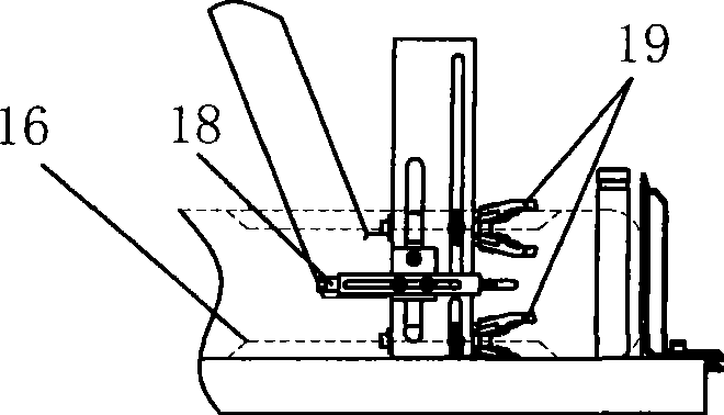
[0031] see Figure 4 , Figure 5 , an embodiment of the method for making a cutting wire of the present invention is to manufacture a cutting wire with a length of 1 m and a diameter of about 2 mm as an example. Cut out a steel wire rope 20 with a diameter of φ2mm and a length of about 1m. After alkali cleaning, degreasing and acid cleaning, the steel wire rope 20 is insulated and wrapped in segments with PVC plastic film, so that the wrapped part is insulated and no metal is deposited in the subsequent electroplating process. Binder to maintain the flexibility of the wire rope cutting wire. The width of the bandaged part is about 15mm, and the width of the unbandaged part is also about 15mm. Then, the steel wire rope 20 is pre-plated with a Watt-type nickel plating solution to form a transition layer 23 , the transition layer 23 can improve the bind...


PUM

PropertyMeasurementUnit
diameteraaaaaaaaaa
widthaaaaaaaaaa
diameteraaaaaaaaaa

Abstract

The invention provides a method for manufacturing a cutting wire and the cutting wire, and the method is characterized by taking a steel wire rope as the substrate and consolidating the abrasive material on the steel wire rope substrate by using metal binder or resinoid bond in electroplating manner. The abrasive material is normal or super hard abrasive material of different grain sizes. The processing technology of the cutting wire is reasonable, and the manufactured cutting wire has wide cutting range, good cutting quality and little pollution. The invention also provides a tire cutting device, comprising a lathe bed, a sliding working table which is provided with a fixture, an annular cutting device, driving wheels, driven wheels, a strainer for the annular cutting device and a cutting motor. The device is characterized in that the annular cutting device is an annular cutting wire which takes the steel wire rope as the substrate and consolidates the abrasive material on the surface. The driving wheels and the driven wheels have two sets and drive the two cutting wires to rotate synchronously, thus forming the double-cut cutting. The device has the advantages of high cutting efficiency, good cutting quality and little pollution.

Description

technical field [0001] The invention belongs to the technical field of cutting tools and equipment manufacturing, in particular to a method for making a cutting wire, a cutting wire and a tire cutting device. Background technique [0002] With the development of science and technology, due to the high wear resistance, high corrosion resistance, high oxidation resistance, high hardness, high resistivity, high temperature resistance and non-conductive properties of precious hard and brittle materials such as gems, agate, ceramics and crystals. Magnetic and other properties, its application scope has gradually expanded from industries such as arts and crafts to aerospace, light industry, machinery, chemical industry and other industrial fields, giving play to the incomparable advantages of metal materials. In addition, the application of rubber, plastic, and other high-toughness polymer composite materials is becoming more and more extensive. However, hard and brittle material...

Claims


Application Information

Patent Timeline
Patent Type & Authority Applications(China)
IPC IPC(8): B28D1/22B24D17/00B26D1/547B26D5/08B24D99/00
Inventor 于国庆高伟
Owner 青岛厚泽锦业技术有限公司
Learn More