
Cone beam double-helix CT Scanning and imaging method for large sized object

A CT scanning and double helix technology, applied in the field of cone beam double helix CT scanning imaging, can solve the problems of increasing the difficulty of mechanical realization, the transverse beam angle of the radiation source cannot include the cross section of the object, and cannot meet the detection needs, etc.

Inactive Publication Date: 2009-03-25
CHONGQING UNIV
View PDF0 Cites 19 Cited by
  • Summary
  • Abstract
  • Description
  • Claims
  • Application Information

AI Technical Summary

Problems solved by technology

However, the lateral size of the object to be detected is often large, and the transverse beam angle of the radioactive source cannot cover the cross section of the object. At this time, the conventional cone beam helical scanning method cannot meet the detection needs.
[0003] In order to solve the above problems, the cone-beam CT in which the ray source and detector are extended from one offset to three offsets appears, but the object needs to be translated in the direction perpendicular to and parallel to the central ray during scanning, and the ray source and detector need to be deflected synchronously , which increases the difficulty of mechanical realization, and the obtained projection data is incomplete projection data. Using the symmetry of parallel beam scanning to rearrange the projection data into parallel beams will cause rearrangement errors; there is also a dual-source double-helix scan method, two sets of ray sources and detectors are used to scan the object along the upward and downward parallel helical trajectories. This scanning method can only improve the detection efficiency of long objects, but cannot solve the detection problem of objects with large lateral dimensions.

Method used


Image

  • Cone beam double-helix CT Scanning and imaging method for large sized object
  • Cone beam double-helix CT Scanning and imaging method for large sized object
  • Cone beam double-helix CT Scanning and imaging method for large sized object

Examples


Embodiment Construction

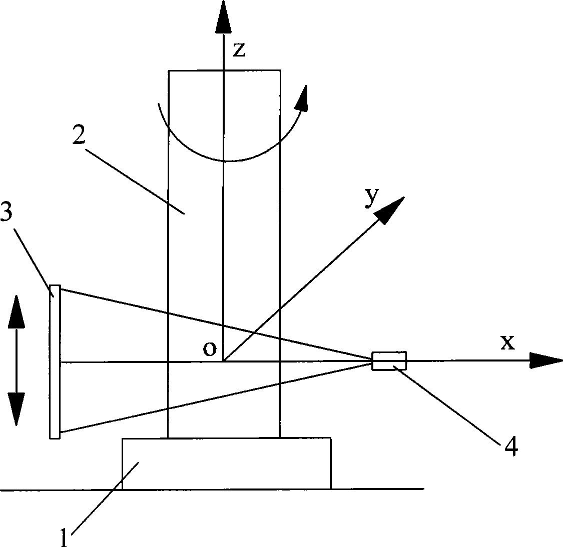
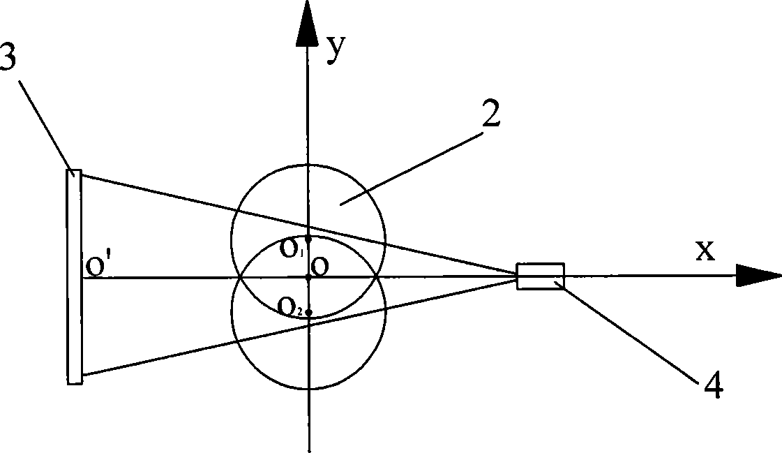
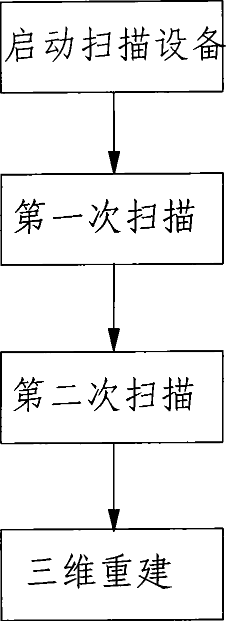
[0030] figure 1 It is a structural schematic diagram of the present invention, figure 2 It is a cross-sectional schematic diagram of the scanning of the workpiece to be detected in the present invention, image 3 It is a block diagram of the scanning imaging method of the present invention, as shown in the figure: the cone-beam double-helical CT scanning imaging method for large-sized objects in this embodiment, the workpiece 2 to be detected is set on the rotary table 1, and the central axis of the rotary table 1 is at the initial position It is perpendicular to and intersects with the central ray of the ray source 4, and the intersection point of the central axis of the rotary table 1 and the central ray of the ray source 4 at the initial position is used as the origin to establish a rectangular coordinate system, and the y-axis is along the horizontal direction of the rotary table 1 and perpendicular to the ray The coordinate axis of the central ray of the source, the z-a...


PUM


Abstract

The invention discloses a cone-beam double-spiral CT scanning and imaging method for a large-sized object. The method comprises the following steps: after a turntable provided with a work piece to be detected translates twice along the direction vertical to a central ray, and the work piece and the turntable rotate around a rotating shaft; meanwhile, a ray source and a detector lift and scan along the direction of the rotating shaft to form parallel double-spiral scanning tracks and acquire a three-dimensional image of an area to be detected through a three-dimensional reconstruction method improved by the invention. The method realizes the detection of large objects by using the structure of the prior CT machine, the ray source and the detector do not need to deflect, and the turntable and the work piece to be detected do not need to translate along the radial direction (in the direction parallel to the central ray), so the scanning process is easy to realize mechanically, the transverse size of the detected object doubles that of the prior single-spiral CT, complete projection data of the object can be acquired, and the detection for long objects with large transverse sizes can be realized; and the method does not need to rearrange and interpolate projection data, has high detection precision, only scans the spiral track twice, and has high detection efficiency.

Description

technical field [0001] The invention relates to a CT scanning imaging method, in particular to a cone-beam double-helical CT scanning imaging method for large-sized objects. Background technique [0002] In CT detection technology, the cone beam helical scanning method and the corresponding imaging method can solve the detection problem of long objects, with high detection efficiency and good axial resolution. However, the lateral size of the object to be detected is often large, and the lateral beam angle of the radioactive source cannot cover the cross-section of the object. At this time, the conventional cone beam helical scanning method cannot meet the detection needs. [0003] In order to solve the above problems, the cone-beam CT in which the ray source and detector are extended from one offset to three offsets appears, but the object needs to be translated in the direction perpendicular to and parallel to the central ray during scanning, and the ray source and detecto...

Claims


Application Information

Patent Timeline
IPC IPC(8): G01N23/04G03B42/02
Inventor 曾理邹晓兵
Owner CHONGQING UNIV
Learn More