Silicon rubber sleeve expansion method and device
A silicone rubber sleeve and expansion device technology, which is applied to tubular objects, other household appliances, household appliances, etc., can solve problems affecting the contact of cold-shrinkable terminal parts, cracking of cold-shrinkable sleeves, cracking of silicone rubber tubes, etc., and achieve mechanical Easy processing, clean expansion work, and easy operation
- Summary
- Abstract
- Description
- Claims
- Application Information
AI Technical Summary
Problems solved by technology
Method used
Image

Examples
Embodiment 1
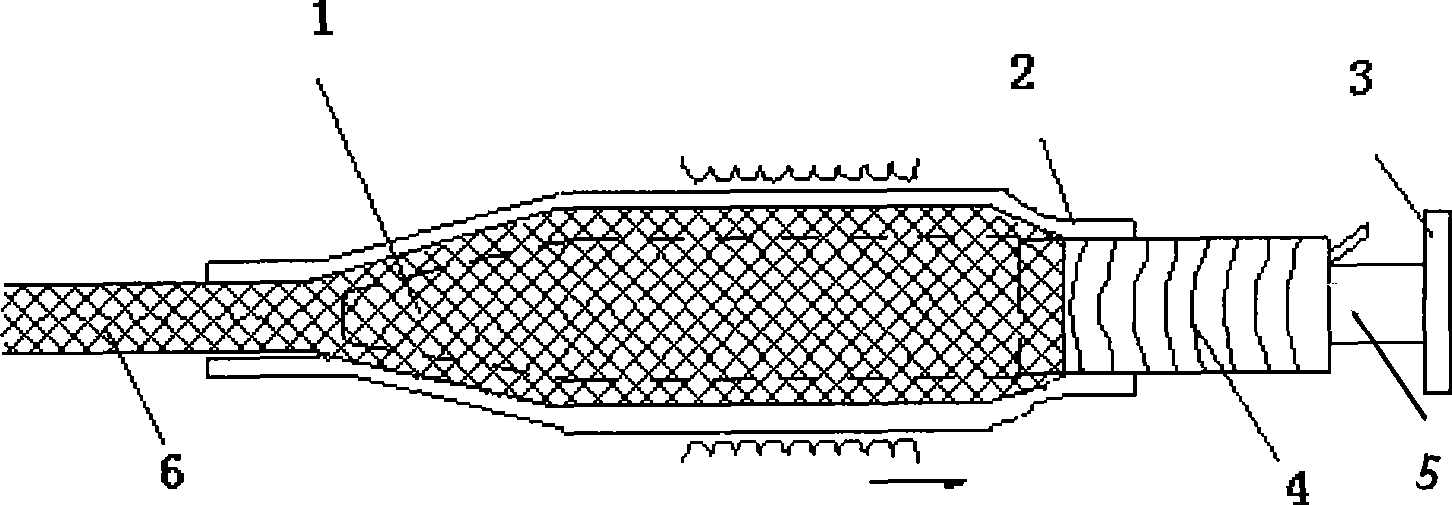
[0026] Such as figure 1 As shown, the silicone rubber sleeve expansion device is characterized in that: the tail end of the expansion head 1 has a cavity, the spiral support tube 4 is inserted into the cavity, and has a mandrel 5 that can hold the spiral support The tube 4, the ejector rod 5 and the ejector rod support 3 are plug-in connections, and a nylon mesh sleeve 6 is used as a spacer between the silicone rubber tube 2 and the expansion head 1.
[0027] The specific method is as follows:
[0028] 1. Fix the top rod support of the metal structure on the wall or other side of the base that can bear the thrust within 100KG in the horizontal direction;
[0029] 2. Adjust the specifications of the iron expansion head and spiral support tube to correspond to the size to be expanded, and insert the spiral support tube into the tail cavity of the iron expansion head;
[0030] 3. Insert the ejector rod together with the spiral tube into the ejector rod support. After confirming that the...
Embodiment 2
[0036] 1. Fix the top rod support of the metal structure on the wall or other side of the base that can bear the thrust within 100KG in the horizontal direction;
[0037] 2. Adjust the specifications of the steel expansion head and spiral support tube to correspond to the size to be expanded, and insert the spiral support tube into the tail cavity of the steel expansion head;
[0038] 3. Insert the ejector rod together with the spiral tube into the ejector rod support. After confirming that the connection with the ejector rod support is in a proper position, retract the spiral tube into the tail cavity of the ejector rod to expose the spiral tube at a distance of 45mm;
[0039] 4. Select the propylene rubber sleeve and the strong PE wire mesh sleeve of the corresponding size, feed the nylon mesh sleeve into the propylene rubber tube, and expose the strong PE wire mesh sleeve 15mm toward the end of the ejector support;
[0040] 5. Put one end of the strong PE wire mesh sleeve on the exp...
Embodiment 3
[0044] 1. Fix the top rod support of the metal structure on the wall or other side of the base that can bear the thrust within 100KG in the horizontal direction;
[0045] 2. Adjust the specifications of the aluminum expansion head and spiral support tube to correspond to the size to be expanded, and insert the spiral support tube into the tail cavity of the aluminum expansion head;
[0046] 3. Insert the ejector rod together with the spiral tube into the ejector rod support. After confirming that the connection with the ejector rod support is in a proper position, retract the spiral tube into the tail cavity of the ejector rod, exposing the spiral tube at a distance of 50mm;
[0047] 4. Choose the natural rubber sleeve and the strong PET wire mesh sleeve of the corresponding size, feed the PET wire mesh sleeve into the natural rubber tube, and expose the PET wire mesh sleeve 20mm toward the end of the ejector support;
[0048] 5. Put one end of the PET wire mesh sleeve on the aluminum ...
PUM
 Abstract
Description
Claims
Application Information
 - R&D
- Intellectual Property
- Life Sciences
- Materials
- Tech Scout
- Unparalleled Data Quality
- Higher Quality Content
- 60% Fewer Hallucinations
Browse by: Latest US Patents, China's latest patents, Technical Efficacy Thesaurus, Application Domain, Technology Topic, Popular Technical Reports.
© 2025 PatSnap. All rights reserved.Legal|Privacy policy|Modern Slavery Act Transparency Statement|Sitemap|About US| Contact US: help@patsnap.com