Coated optical fiber ribbon
A technology of optical fiber ribbon and optical fiber, applied in the direction of glass optical fiber, clad optical fiber, optics, etc., can solve the problems of lack of flame retardancy and shielding characteristics, and achieve flame retardancy, good flame retardancy, and good shielding characteristics Effect
- Summary
- Abstract
- Description
- Claims
- Application Information
AI Technical Summary
Problems solved by technology
Method used
Image

Examples
Embodiment approach 1
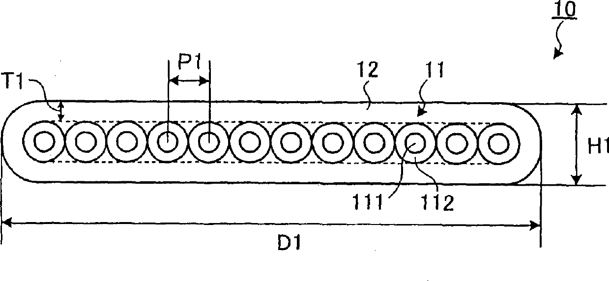
[0024] figure 1 is a cross-sectional view schematically showing the optical fiber ribbon according to Embodiment 1 of the present invention. Such as figure 1 As shown, the optical fiber ribbon 10 of Embodiment 1 is formed by arranging 12 optical fiber strands 11 with a layer of strand covering 112 formed on the outer periphery of a glass optical fiber 111 in parallel, and covering them together with the ribbon covering 12. of.
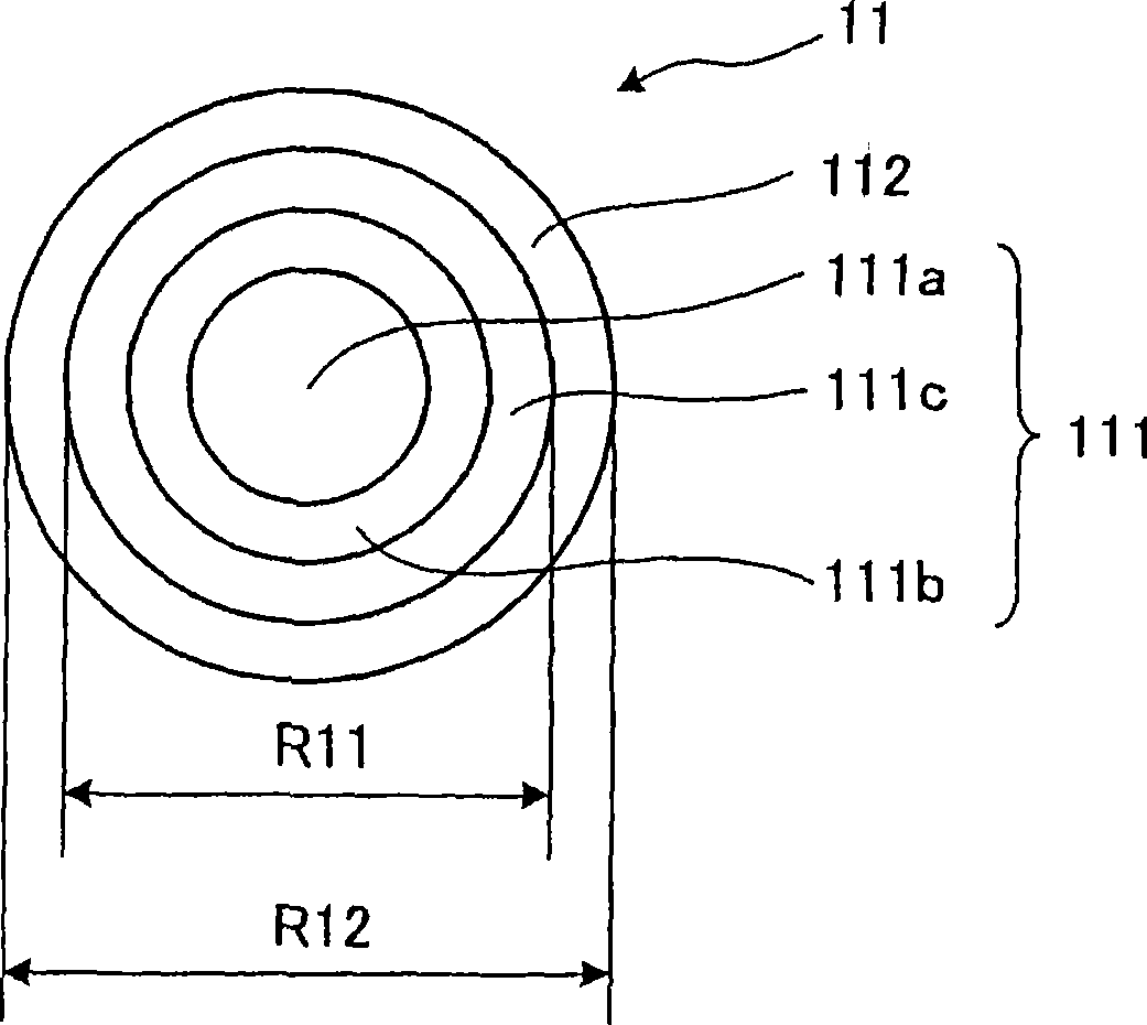
[0025] in addition, figure 2 yes figure 1 A cross-sectional view of an optical fiber strand 11 is shown. The outer diameter R11 of the glass optical fiber 111 is 55 to 90 μm. Therefore, as a small diameter smaller than that of a normal optical fiber having an outer diameter of 125 μm, it is possible to improve accommodation and reduce the probability of breakage due to bending, and to form a small diameter to such an extent that transmission loss does not increase. The glass optical fiber 111 will be described later.
[0026] In addition, the Y...
Embodiment approach 2
[0046] Next, the optical fiber ribbon in Embodiment 2 of the present invention will be described. Figure 4 is a cross-sectional view schematically showing an optical fiber ribbon in Embodiment 2 of the present invention. Such as Figure 4 As shown, the optical fiber ribbon 20 in Embodiment 2 is formed by arranging 12 optical fiber strands 21 with a strand cover 212 formed on the outer periphery of a glass optical fiber 211 in parallel, and covering them collectively with the ribbon cover 22 of.
[0047] Figure 5 yes Figure 4 A cross-sectional view of an optical fiber strand 21 is shown. Like the optical fiber strand 11 in Embodiment 1, the optical fiber strand 21 has a strand cover 212 formed on the outer periphery of the glass optical fiber 211 . In addition, the glass optical fiber 211 is a single-mode optical fiber having a generally stepped refractive index profile having a central core 211a and a clad 211b formed around the central core 211a. In addition, the out...
Embodiment 1~3、 comparative example 1~4
[0056] As Examples 1 to 3 and Comparative Examples 1 to 4 of the present invention, optical fiber ribbons were produced. 7 shows the characteristics of the optical fiber strand, the characteristics of the optical fiber ribbon, the total thickness of the flame-retardant coating, the burning test, and the shielding test for the optical fiber ribbons in Examples and Comparative Examples of the present invention. The result of , and the graph of the evaluation of containment.
[0057] In Fig. 7, regarding Examples 1 and 2 where the strand covering is composed of one layer, this covering is referred to as the "second layer", and regarding Example 3 where the strand covering is composed of a non-flammable layer and a flame-retardant layer And Comparative Examples 1-4, let a non-flame-retardant layer be a "1st layer", and let a flame-retardant layer be a "2nd layer." In addition, [UV] means a non-flammable ultraviolet curable resin, and "flame retardant" means a flame retardant ultr...
PUM
| Property | Measurement | Unit |
|---|---|---|
| diameter | aaaaa | aaaaa |
| width | aaaaa | aaaaa |
| diameter | aaaaa | aaaaa |
Abstract
Description
Claims
Application Information
 - R&D
- Intellectual Property
- Life Sciences
- Materials
- Tech Scout
- Unparalleled Data Quality
- Higher Quality Content
- 60% Fewer Hallucinations
Browse by: Latest US Patents, China's latest patents, Technical Efficacy Thesaurus, Application Domain, Technology Topic, Popular Technical Reports.
© 2025 PatSnap. All rights reserved.Legal|Privacy policy|Modern Slavery Act Transparency Statement|Sitemap|About US| Contact US: help@patsnap.com