Method for directly fluid coking oil sand and apparatus
A fluidized bed and oil sand technology, which is applied in the petroleum industry and the preparation of liquid hydrocarbon mixtures, etc., can solve the problems of secondary pollution and difficulty in large-scale continuous production of gasification technology, and achieve high comprehensive utilization and quality improvement. Effect
- Summary
- Abstract
- Description
- Claims
- Application Information
AI Technical Summary
Problems solved by technology
Method used
Image
Examples
Embodiment 1
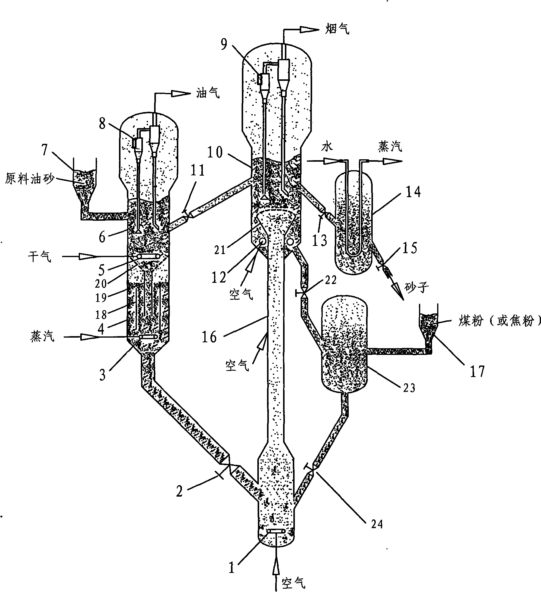
[0037] See attached figure 1 , the oil sand direct fluidized bed coking device of the present embodiment comprises: coking reactor 6, circulation stripper 4, dilute-phase coking tube 16, dense-phase coking reactor 10, external heat extractor 14, feeder 7 and 17, cyclone separators 8 and 9, mixing heat exchange tank 23, shower head distributor 21, control valves 2, 11, 13, 15, 22 and 24, gas distributors 1, 3, 5 and 12, draft tube 18, center feeding pipe 19, sieve plate 20. The feeder 7 is connected to the coking reactor 6, a cyclone separator 8 is set in the settling space on the upper part of the coking reactor 6, a fluidization gas distributor 5 is set in the lower part, and a circulation stripper 4 is coaxially set directly below, and the coking reactor 6 and An inverted conical sieve plate 20 is arranged between the circulation stripper 4, and the center of the sieve plate 20 is connected to the central feeding pipe 19. The sieve plate 20 plays the role of supporting the ...
Embodiment 2
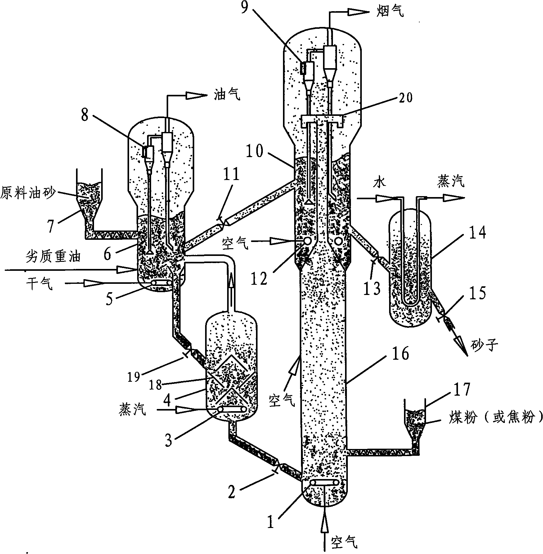
[0041] See attached figure 2 , the oil sand direct fluidized bed coking device of the present embodiment comprises: a coking reactor 6, a stripper 4, a dilute-phase coking tube 16, a dense-phase coking reactor 10, an external heat extractor 14, a feeder 7 and 17. Cyclone separators 8 and 9, control valves 2, 11, 13, 15 and 19, gas distributors 1, 3, 5 and 12, baffle 18 and quick separator 20. The feeder 7 is connected with the coking reactor 6, and the inferior heavy oil nozzle is installed outside the coking reactor 6, the cyclone separator 8 is arranged in the upper part of the settling space, and the fluidization gas distributor 5 is arranged in the lower part. The lower part of the coking reactor 6 is connected to the stripper 4 through an inclined pipe with a control valve 19, and a baffle 18 is set inside the stripper 4, and its function is to prolong the contact time between the particles and the stripping gas. Stripping steam distributor 3. The bottom of the strippe...
Embodiment 3
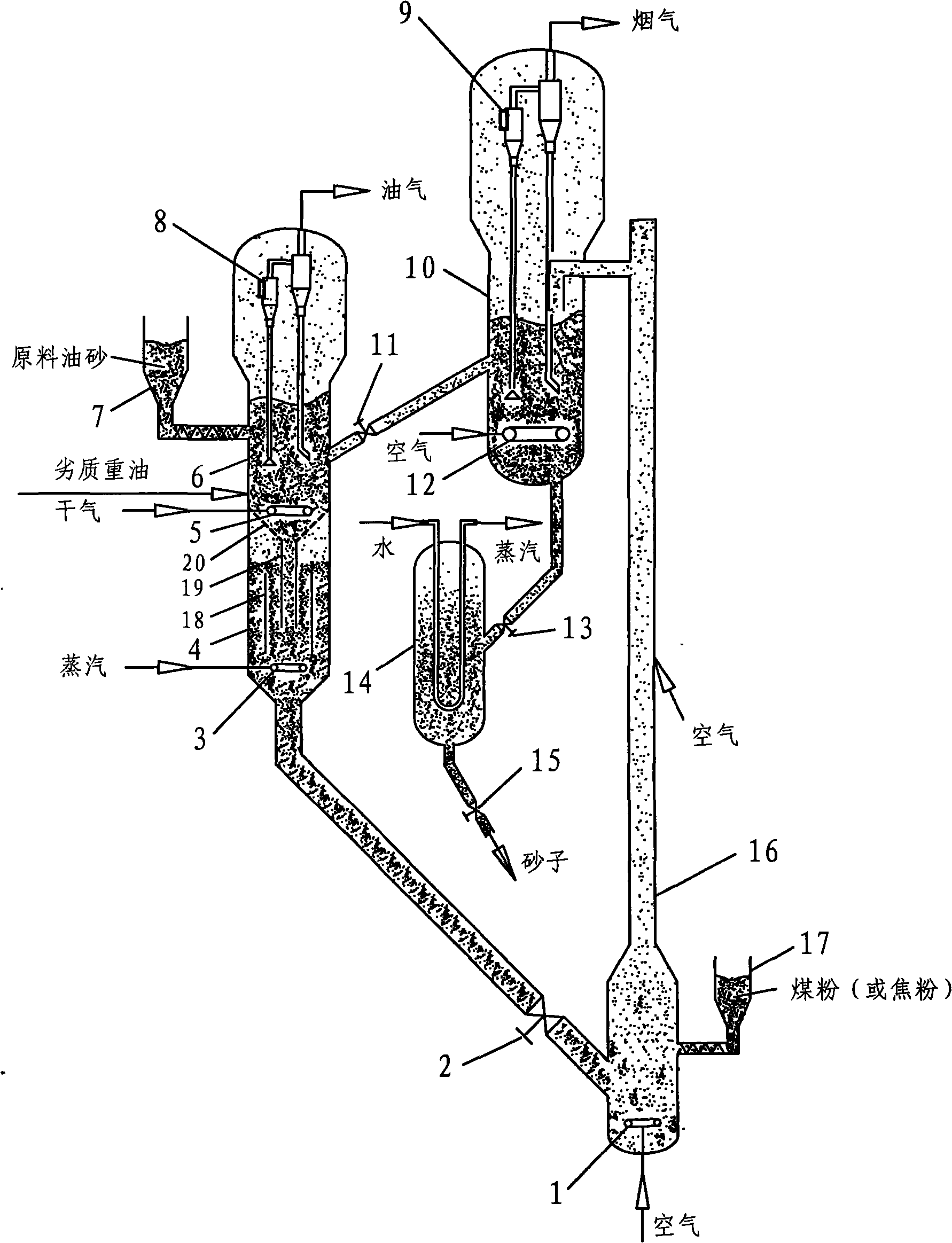
[0044] See attached image 3 , the oil sand direct fluidized bed coking device of the present embodiment comprises: coking reactor 6, circulation stripper 4, dilute-phase coking tube 16, dense-phase coking reactor 10, external heat extractor 14, feeder 7 and 17, cyclone separators 8 and 9, control valves 2, 11, 13 and 15, gas distributors 1, 3, 5 and 12, draft tube 18, central feeding pipe 19, sieve plate 20. The feeder 7 is connected to the coking reactor 6, and the low-quality heavy oil feeding nozzle is installed outside the coking reactor 6, the cyclone separator 8 is installed in the upper part of the settling space, the fluidization gas distributor 5 is arranged in the lower part, and the circulation stripper is coaxially arranged directly below 4. An inverted conical sieve plate 20 is set between the coking reactor 6 and the circulating stripper 4. The center of the sieve plate 20 is connected to the central feeding pipe 19. On the one hand, the sieve plate 20 plays a r...
PUM
 Abstract
Description
Claims
Application Information
 - Generate Ideas
- Intellectual Property
- Life Sciences
- Materials
- Tech Scout
- Unparalleled Data Quality
- Higher Quality Content
- 60% Fewer Hallucinations
Browse by: Latest US Patents, China's latest patents, Technical Efficacy Thesaurus, Application Domain, Technology Topic, Popular Technical Reports.
© 2025 PatSnap. All rights reserved.Legal|Privacy policy|Modern Slavery Act Transparency Statement|Sitemap|About US| Contact US: help@patsnap.com


