
Optical reading head

An optical reading head and light source technology, applied in the field of optical reading heads, can solve the problems such as the inability to effectively increase the allowable range of the inclination angle, reduce the LED usage and power consumption, and effectively improve the lighting efficiency, so as to improve the lighting efficiency. and identification ability, eliminating the dead angle of identification, and the effect of convenient assembly

Inactive Publication Date: 2008-12-10
SUNPLUS MMEDIA
View PDF0 Cites 11 Cited by
  • Summary
  • Abstract
  • Description
  • Claims
  • Application Information

AI Technical Summary

Problems solved by technology

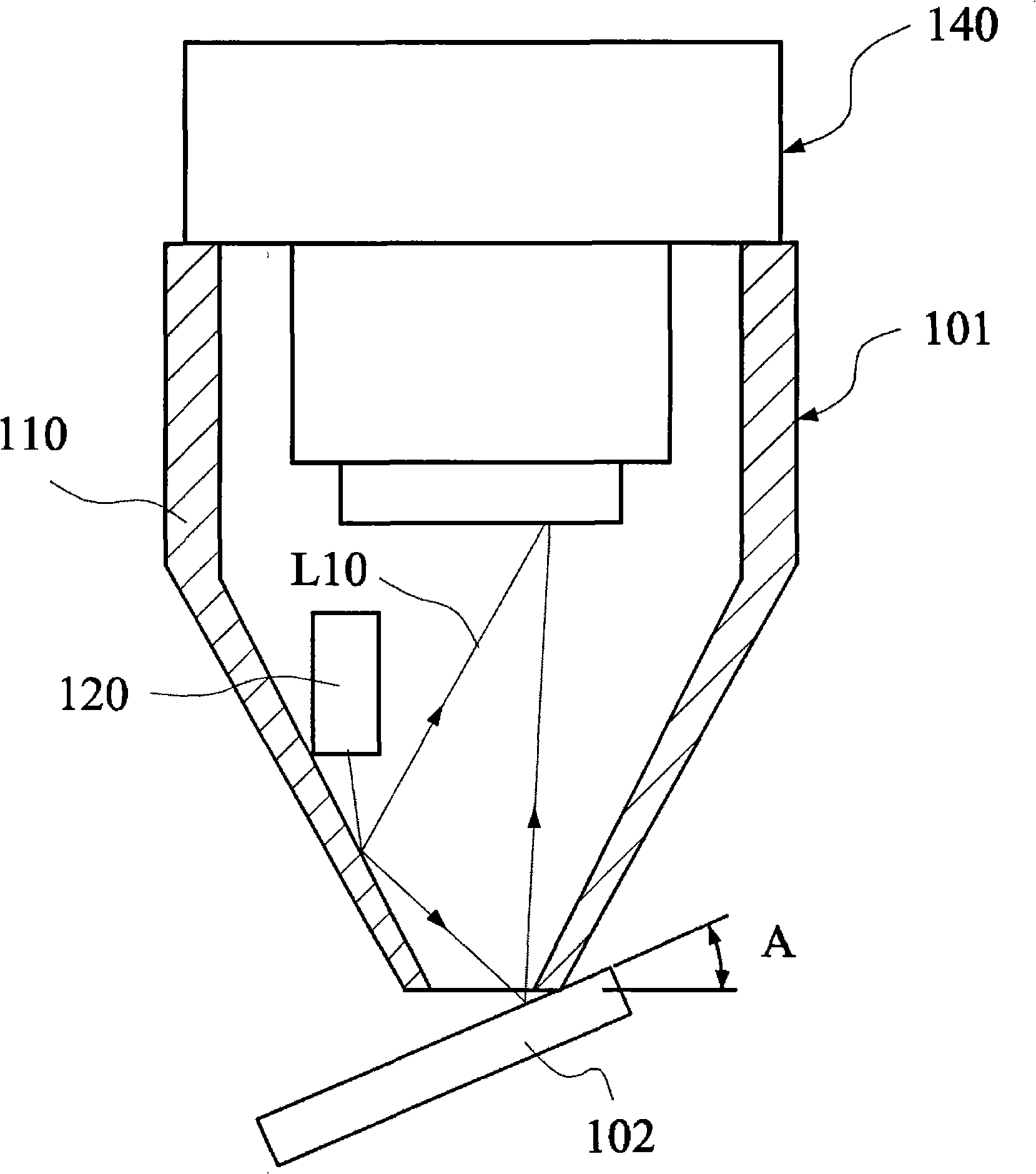
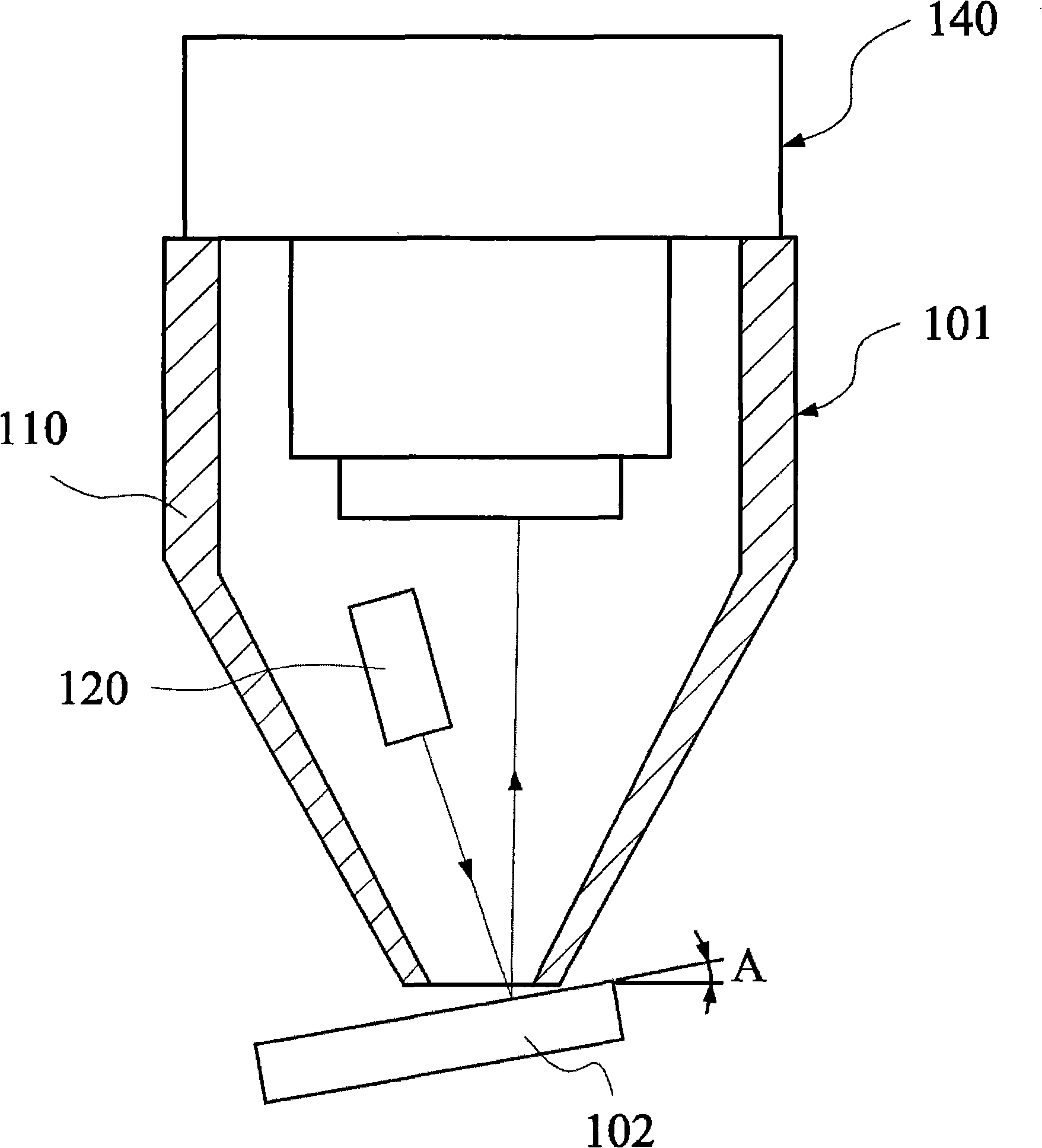
figure 2 The optical read head of the figure 1 , the difference is that the light from the LED 120 as the light source module directly hits the object 102, which is very likely to cause reflected strong light to enter the photosensitive module 140 and further reduce the contrast.
[0008] Therefore, the disadvantages of the optical pickup head in the prior art are that it is impossible to avoid the dead angle of identification caused by reflected strong light, it is impossible to effectively improve the lighting efficiency to reduce the usage and power consumption of LEDs, and it is impossible to effectively increase the allowable range of the tilt angle.
In addition, the assembly of prior art optical read heads is quite complex

Method used


Image

  • Optical reading head
  • Optical reading head
  • Optical reading head

Examples


Embodiment Construction

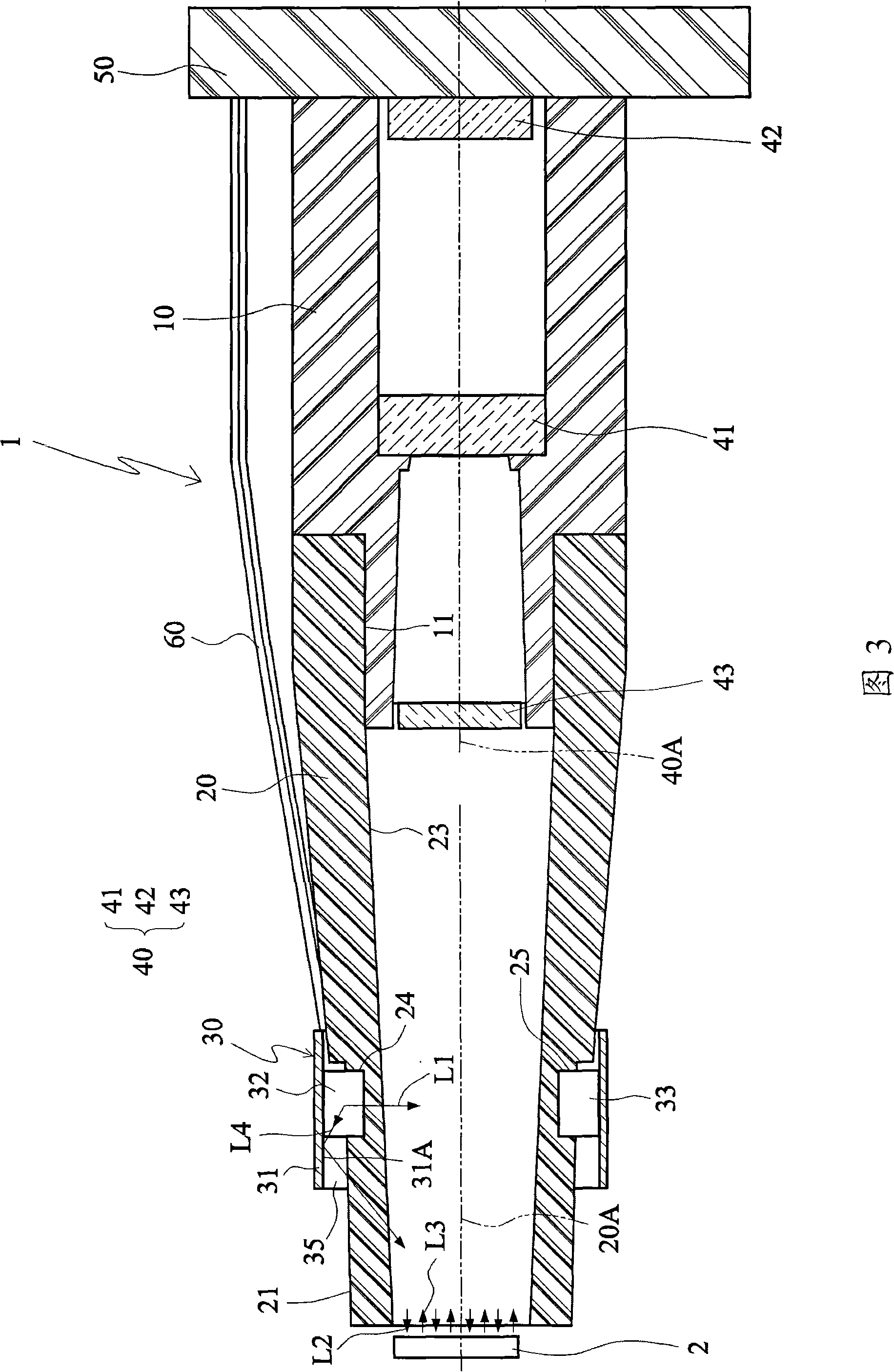
[0060] FIG. 3 is a schematic diagram of the application of the optical pickup head in the first embodiment of the present invention. As shown in FIG. 3 , the optical pickup head 1 of this embodiment is used to read an image of an object 2 . The object 2 is, for example, an electronic book on which a pattern such as a two-dimensional barcode is printed. The optical pickup head 1 includes a casing 10 , a diffusion structure 20 , a light source module 30 and a photosensitive module 40 .

[0061] The diffusing construction 20 is connected to the housing 10 . In FIG. 3 , the diffusion structure 20 can be a hollow body or a hollow tube, and can be used as a light integrating sphere. However, the diffusing formation 20 may also be a solid body or a solid cylinder. Diffuse construction 20 may have a circular, square, or other cross-sectional shape. When the diffusing construction 20 has a circular cross section, the substrate 31 surrounds the diffusing construction 20 more than 36...


PUM


Abstract

An optical pickup head is provided, which is utilized for picking up the image of an object. The optical pickup head comprises a shell body, a diffusion structure, an optical source module and a sensitization module. The diffusion structure is connected with the shell body. The optical source module is provided with a basal plate and a first optical source positioned on the facade of the basal plate. The facade of the basal plate is positioned on the external surface of the diffusion structure. The first optical source provides an initial light ray and casts the light ray into the diffusion structure. Then, the diffusion structure processes the initial light ray into an equalized light ray and transmits the processed light ray. The sensitization module is positioned inside the shell body to sense a reflected light ray which is produced when the equalized light ray is reflected by the object. Therefore, the invention can be applied to eliminate the identification dead corner resulted from strong reflected light ray, enhance the lighting efficiency, reduce the number of optical sources and consumption of electric power, improve the evenness of lighting and improve the allowed scope for inclined angle.

Description

technical field [0001] The invention relates to an optical pickup head. Background technique [0002] figure 1 It is an application schematic diagram of a traditional optical pickup head. Such as figure 1 As shown, the optical pickup head 101 is used to read the object 102 , wherein the optical pickup head 101 includes a hollow shell 110 , a light source module 120 and a photosensitive module 140 . The light source module 120 is fixed in the hollow casing 110 and provides light. The light irradiates the object 102 after being reflected in the hollow casing 110 . The photosensitive module 140 is fixed in the hollow casing 110 for sensing light reflected by the object 102 . [0003] The reflection of light can be divided into three forms, namely specular reflection, diffuse reflection and diffuse reflection. Specular reflection means that the angle of incidence of light rays is equal to the angle of reflection. Diffuse reflection occurs when an uneven surface reflects l...

Claims


Application Information

Patent Timeline
IPC IPC(8): G06K7/10G02B6/00G02B7/00
Inventor 吴智孟
Owner SUNPLUS MMEDIA
Learn More