Last stage pressure reducing device

A decompression device and pressure reducer technology, which is applied in the direction of oil supply device, charging system, internal combustion piston engine, etc., can solve the problems of small engine displacement, exhaust gas not up to standard, insufficient combustion, etc., and achieve mobility Strong, low fuel consumption, fast response effect

Inactive Publication Date: 2008-10-01
SHANGHAI ZHONGYOU ENTERPRISE GRP CO LTD +1
View PDF0 Cites 0 Cited by
  • Summary
  • Abstract
  • Description
  • Claims
  • Application Information

AI Technical Summary

Problems solved by technology

However, the displacement of small engines is small, the cost of multiple components used in the combustion system is high, and the air supply volume is large, resulting in insufficient combustion, exhaust emissions that are not up to standard, and air pollution.

Method used


Image

  • Last stage pressure reducing device
  • Last stage pressure reducing device
  • Last stage pressure reducing device

Examples


Embodiment Construction

[0019] In order to make the technical means, creative features, goals and effects achieved by the present invention easy to understand, the present invention will be further described below in conjunction with specific illustrations.

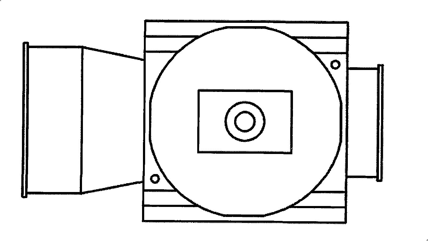
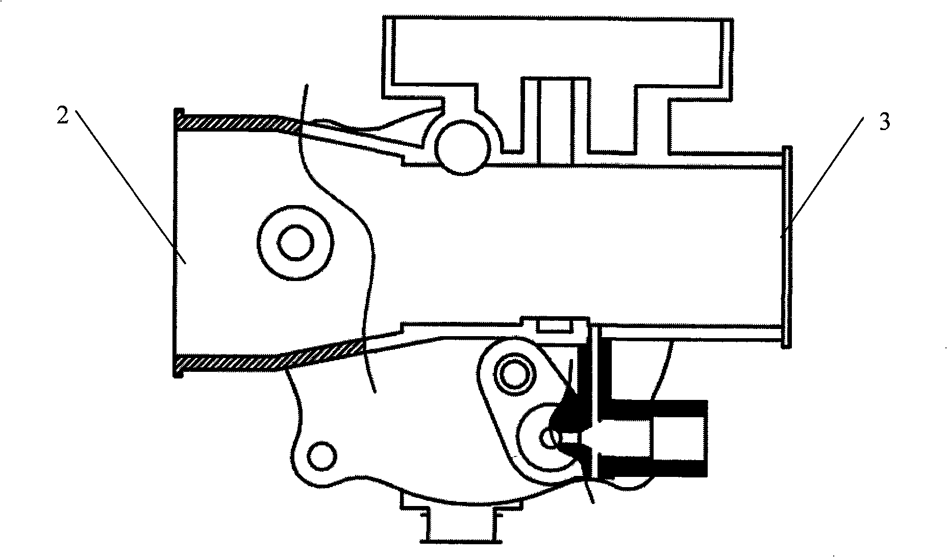
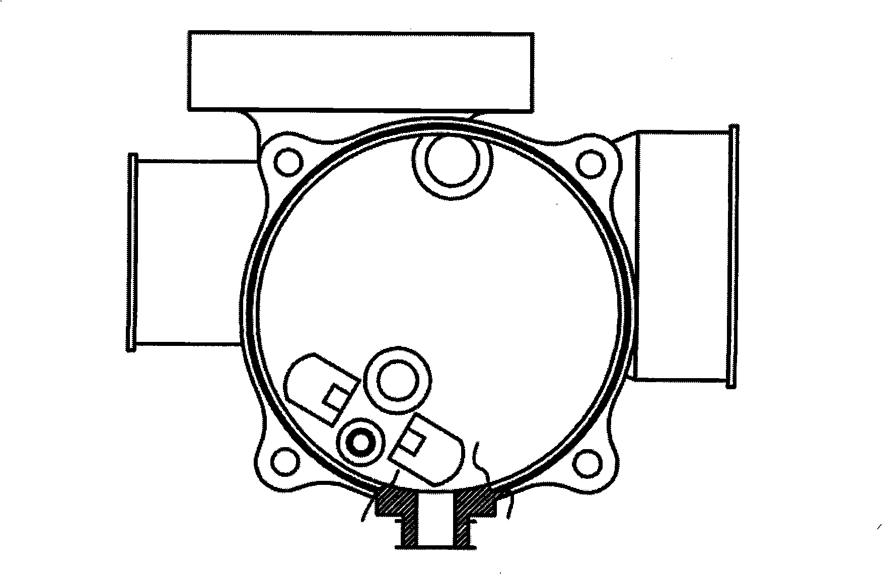
[0020] see Figure 1 to Figure 5 , the final decompression device, including a pressure reducer, a primary decompression gas pipeline, a secondary decompression gas pipeline and a total gas pipeline, the pressure reducer body has a regulating valve and a mixer, the regulating The valve, mixer and pressure reducer are integrated.

[0021] The regulating valve is arranged at the air inlet position of the pressure reducer.

[0022] The mixer is arranged downstream of the pressure reducer.

[0023] As shown in the figure, the gas inlet 1 of the pressure reducer, the air inlet 2, the engine interface 3, the regulating valve 4 (not shown in the figure), and the mixer 5 (not shown in the figure) are arranged on the pressure reducer Inside the body. ...


PUM


Abstract

The invention relates to a last-stage reducer, comprising a reducer, a first stage reduction gas pipeline, a second stage reduction gas pipeline and a gas manifold, characterized in that the reducer body is provided with a regulating valve and a mixer, the regulating valve, the mixer and the reducer are integrated together. The reducer reduces the pressure of gas to negative pressure, and then the gas is absorbed into the combustion chamber of an engine. The mixer mixes the gas and air into flammable gas. The regulating valve regulates the pressure of input gas. Compared with the prior art, the gas system integrates the regulating valve, the mixer and the reducer together, has the characteristics of strong mobility and fast reaction, the shape of the gas reducer is designed according to Wenquli principle, after the pressure is reduced, the gas is in negative pressure state and absorbed into the engine, the air-fuel ratio is adjusted precisely, the emission is low, the fuel consumption is small; the invention is used specifically for a positive pressure idling system, and enables the positive pressure idling system to start up fast and idle stably.

Description

technical field [0001] The invention relates to a fuel gas system of an engine, in particular to a final-stage decompression device using gas as an energy source. Background technique [0002] The gas engine is an environmentally friendly engine that does not emit black smoke and has low emissions of harmful gases. With the aggravation of the oil crisis and environmental pollution worldwide, the demand for this environmentally friendly gas engine is becoming more and more urgent. [0003] The fuel system for gas engine includes, pressure reducer, regulating valve, mixer, etc. Then the combustion gas is sent into the cylinder. However, the displacement of small engines is small, the cost of multiple components used in the combustion system is high, and the air supply volume is large, resulting in insufficient combustion, substandard exhaust gas, and air pollution. Contents of the invention [0004] The technical problem to be solved by the present invention is to provide a...

Claims


Application Information

Patent Timeline
Patent Type & Authority Applications(China)
IPC IPC(8): F02M21/04
CPCY02T10/32Y02T10/30
Inventor 杨增清
Owner SHANGHAI ZHONGYOU ENTERPRISE GRP CO LTD
Why Eureka
Try Eureka