Control system and control method of gas turbine

A gas turbine and control system technology, which is applied in the direction of control system, gas turbine device, engine control, etc., can solve the problems that cannot be effectively suppressed, and achieve the effect of suppressing the increase of the speed

Inactive Publication Date: 2008-09-17
KAWASAKI HEAVY IND LTD
View PDF3 Cites 10 Cited by
  • Summary
  • Abstract
  • Description
  • Claims
  • Application Information

AI Technical Summary

Problems solved by technology

These efforts have not been able to effectively suppress the occurrence of overspeed when the load is disconnected in the gas turbine power generation equipment fueled by low-calorie gas with continuously changing calorific value.

Method used


Image

  • Control system and control method of gas turbine
  • Control system and control method of gas turbine
  • Control system and control method of gas turbine

Examples


Embodiment Construction

[0027] Embodiments of the gas turbine control system and the gas turbine control method of the present invention will be described below with reference to the drawings.

[0028] Embodiment 1

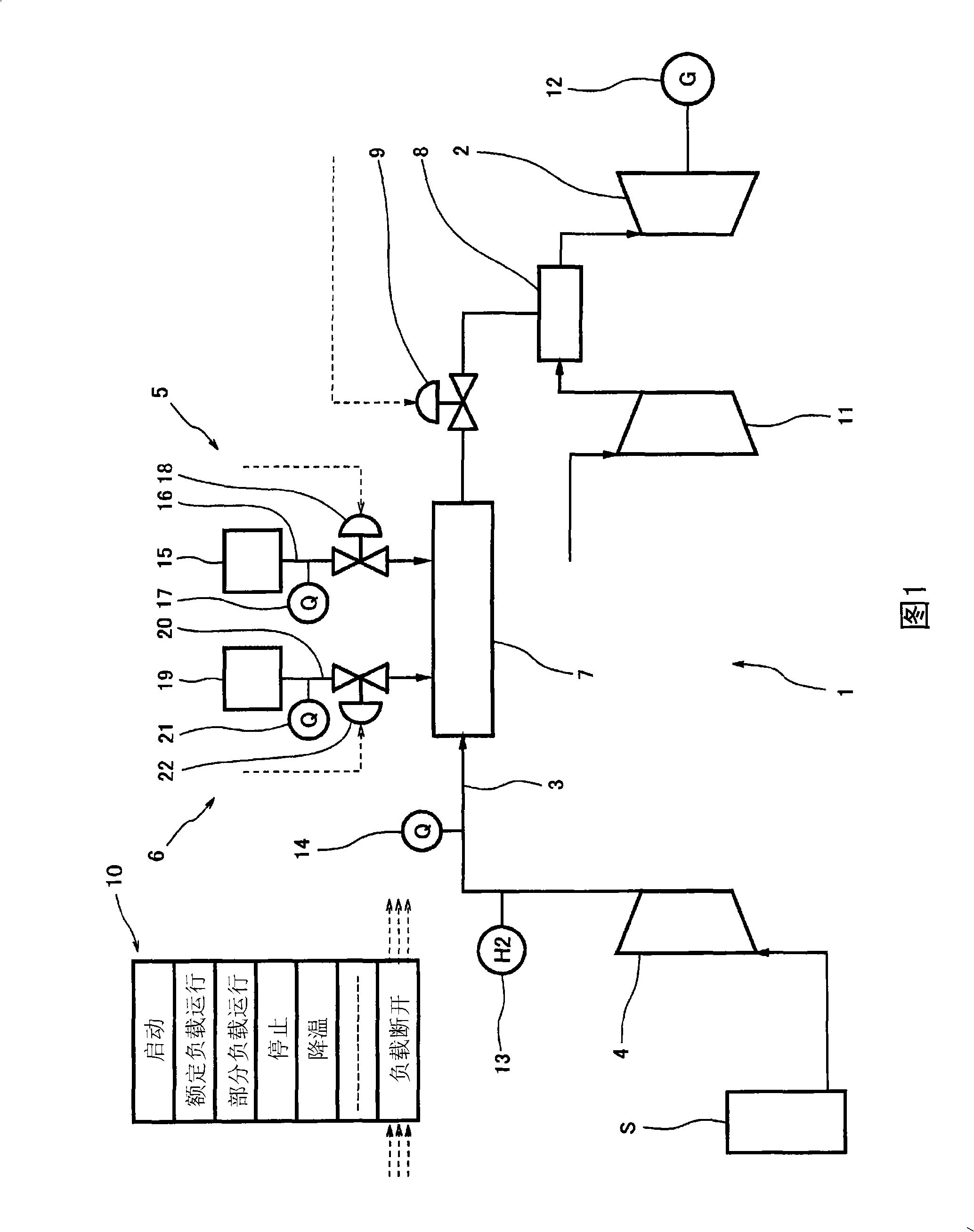
[0029]FIG. 1 is a system diagram schematically showing a gas turbine power plant 1 including an embodiment of a gas turbine control system according to the present invention. This gas turbine power generation facility 1 (hereinafter referred to as the power generation facility 1) is equipped with, as an example, a low calorific value off-product gas (low-calorie gas) generated by a gas generating source S such as a direct reduced iron facility (low-calorie gas) that is continuously changing as fuel. Fuel gas supply pipe 3 for gas turbine 2, fuel compressor 4 for compressing low-calorie gas, heat reduction gas supply device 5 for supplying heat reduction gas to fuel gas supply pipe 3, hydrogen gas for fuel supply A hydrogen gas supply device 6 for the gas supply pipe 3, and a mixer 7 for...


PUM


Abstract

A gas turbine control system which can suppress an increase in rotating speed. of a gas turbine easily upon occurrence of abrupt drop in gas turbine load even if its power generation facility is employing low calorie gas as fuel. The gas turbine control system comprises a fuel flow rate control valve (9) arranged in a passage (3) for supplying fuel gas to the gas turbine (2) in order to regulate the flow rate of fuel gas, a heat reduction gas supply unit (5) for supplying heat reduction gas to the fuel gas supply passage (3), and a system controller (10). In order to decrease the quantity of heat input to the gas turbine (2) when an abrupt drop in load on the gas turbine (2) is detected, the system controller (10) controls heat reduction gas supply operation by the heat reduction gas supply unit (5) in addition to controlling the opening of the fuel flow rate control valve (9).

Description

technical field [0001] The invention relates to a control system and a control method of a gas turbine. More specifically, it relates to a gas turbine control system and a gas turbine control method capable of rapidly controlling the heat entering the gas turbine in order to prevent the gas turbine from exceeding a predetermined rotational speed when a sudden load drop such as load disconnection occurs in gas turbine power generation equipment . Background technique [0002] In the field of iron and steel production, for example, in the case of producing pig iron by the blast furnace method, top gas (ie, blast furnace gas (Blast Furnace Gas), hereinafter abbreviated as BFG) is generated from the blast furnace as a by-product gas with low calorific value. In recent years, due to technical improvements in gas turbines, it is possible to burn by-product gas with low calorific value such as BFG and use it as fuel for gas turbines to generate electricity. On the other hand, in ...

Claims


Application Information

Patent Timeline
IPC IPC(8): F02C9/28F02C7/22F02C9/40F02C9/46
CPCF05D2270/05F05D2270/02F02C9/32F05B2270/101F02C9/28F02C3/20F05B2270/103F02C9/46F02C7/22Y02E20/18F02C9/40
Inventor 佐香正明大田秀明
Owner KAWASAKI HEAVY IND LTD
Why Eureka
Try Eureka