
Heat pipe radiator and high-power LED road lamp

A technology for LED street lamps and cooling devices, which is applied in cooling/heating devices, lighting devices, fixed lighting devices, etc. Very good, the heat dissipation area of ​​the heat sink is not large enough, etc., to achieve the effect of simple structure, easy processing and long service life

Inactive Publication Date: 2008-09-03
孙敬玺
View PDF1 Cites 9 Cited by
  • Summary
  • Abstract
  • Description
  • Claims
  • Application Information

AI Technical Summary

Problems solved by technology

[0002]Traditional road lighting often uses high-pressure sodium lamps, which have two fatal shortcomings of high energy consumption and short life. With the increasing maturity of LED manufacturing technology, LED street lighting Then it came into being, which overcomes the shortcomings of high-pressure sodium lamps, and has the remarkable characteristics of low energy consumption and long life
Most of the high-power LED street lamps in the prior art have heat dissipation problems, and the quality of heat dissipation directly affects the working life and reliability of high-power LED street lamps. The heat generated by the power LED street lamp is directly transmitted to the heat sink, and then radiated out. The main disadvantage of this heat dissipation method is that the heat dissipation area of ​​the heat sink is not large enough, the heat dissipation efficiency is not high enough, and the convection between the heat sink and the air is not very good. good
Heat pipe heat dissipation technology is a heat dissipation method with high heat dissipation efficiency. For example, the patent document with the notification number CN 2068224U discloses a heat pipe radiator, and describes the high efficiency of heat pipe heat dissipation. No examples of applying heat pipe cooling technology to high-power LED street lamps have been found

Method used


Image

  • Heat pipe radiator and high-power LED road lamp
  • Heat pipe radiator and high-power LED road lamp
  • Heat pipe radiator and high-power LED road lamp

Examples


Embodiment Construction

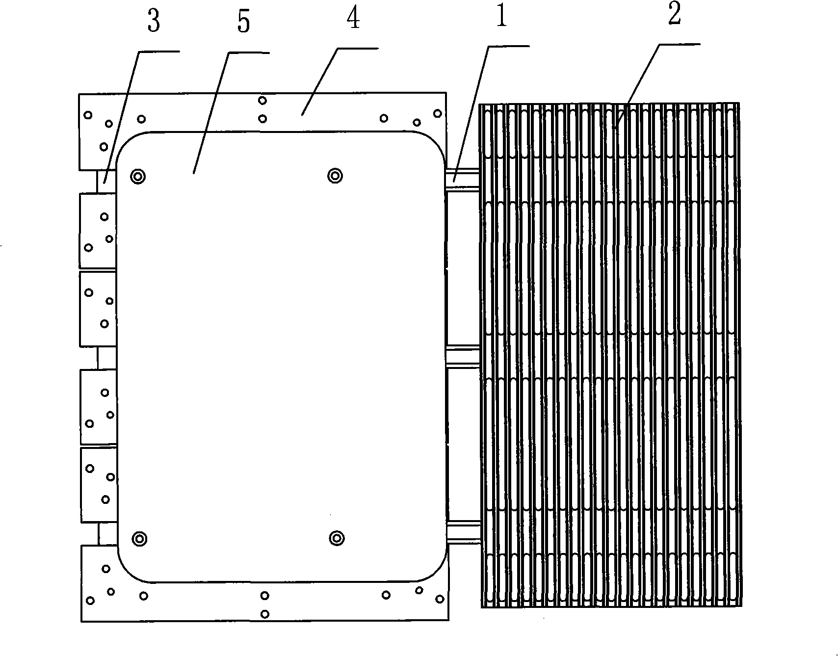
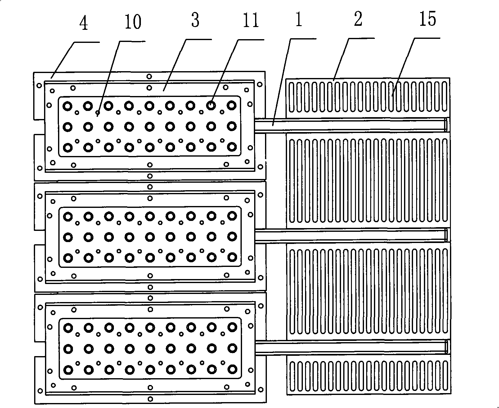
[0029] see Figure 1 to Figure 11 , in the figure, the heat pipe cooling device includes a heat transfer plate, a heat pipe 1 and a heat sink 2, one end of the heat pipe 1 is fixedly connected to the heat transfer plate, the other end of the heat pipe 1 is fixedly connected to the heat sink 2, and the heat transfer plate consists of three aluminum substrates The fixed plate 3, six intermediate fixed plates 4 and the heat pipe pressure plate 5 are stacked together and fixedly connected. The middle fixed plate 4 is located between the aluminum substrate fixed plate 3 and the heat pipe pressure plate 5. One end of the heat pipe 1 is installed on the In the groove formed by the two intermediate fixing plates 4 , the other end of the heat pipe 1 is installed in the groove at the bottom of the heat sink 2 .

[0030] The inside of the heat pipe 1 is sealed with a low boiling point liquid. The inner wall of the heat pipe contains a capillary liquid-absorbing core layer. The heat pipe ...


PUM


Abstract

The invention relates to a lighting device, especially relating to a sinking device and a high-power LED road lamp. A heat pipe sinking device comprises a heat transfer plate, a heat pipe and a fin. The heat transfer plate comprises an amount of aluminium base plate fixation plates, at least two central fixation plates and a heat pipe pressure plate, all of which are stacked together and connected fixedly. The central fixation plate is disposed between the aluminium base plate fixation plate and the heat pipe pressure plate. One end of the heat pipe is disposed in a groove formed by two adjacent central fixation plates, and the other end thereof is disposed in a groove on the bottom of the fin. The high-power LED road lamp comprises the heat pipe sinking device, a casing, a high-power LED luminous tube and an electric power source control circuit. A LED light source provided with the high-power LED luminous pipe is fixed on the aluminium base plate fixation plate. The invention provides a heat pipe sinking device with high heat sinking efficiency, and also provides a high-power LED road lamp having the heat pipe sinking device at the same time.

Description

(1) Technical field: [0001] The invention relates to a lighting appliance, in particular to a heat dissipation device and a high-power LED street lamp. (two), background technology: [0002] Traditional road lighting often uses high-pressure sodium lamps, which have two fatal shortcomings of high energy consumption and short life. With the maturity of LED manufacturing technology, LED street lighting has emerged as the times require, which overcomes the shortcomings of high-pressure sodium lamps. Notable features of low power consumption and long life. Most of the high-power LED street lamps in the prior art have heat dissipation problems, and the quality of heat dissipation directly affects the working life and reliability of high-power LED street lamps. The heat generated by the power LED street lamp is directly transmitted to the heat sink, and then radiated out. The main disadvantage of this heat dissipation method is that the heat dissipation area of ​​the heat sink is...

Claims


Application Information

Patent Timeline
IPC IPC(8): F21V29/00H01L23/367H01L23/427F21S8/00F21V31/00F21V23/00F21W131/103F21Y101/02F21V29/51F21Y115/10
Inventor 孙敬玺张小六范继和唐宗敏
Owner 孙敬玺
Learn More